24�� f3.7 Encased GoTo Dobson
� Andr� Heijkoop
Strijen, NL
http://www.astrosurf.com/aheijkoop/
Contents
Assembly of the roller bearings on
the groundboard
Gluing the toothed belt around the
groundboard
Assembly of the pulley and
servomotor
In height adjustable roller
bearings
View inside the mirrorbox (topview)
Drive wheel inside the mirrorbox
(side view)
View inside the mirrorbox (front
view)
Measuring the place for the drive
wheel inside the altitude bearing sector
Drilling the chamber for the drive
wheel
Measuring the place for the drive
wheel on the mirrorbox
Installing the worm gear reductor
and servomotor
The drive wheel as seen from the
outside
Preface
I always
fancied the big Dobsons and the marvelous images they
show me through the eyepiece.
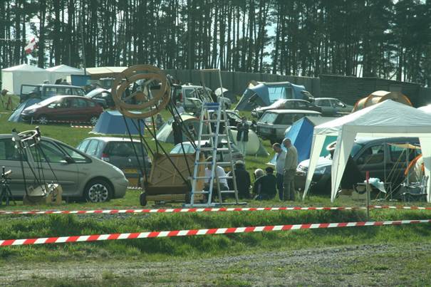
I was sold when I had my first look in 2008 through a 80cm Dobson at a French starparty �the RAP�. I had to climb a wobbly ladder, but the
views are still printed in my memories.
At that
time I had a nice 14� f5.7 truss Dobson on a homemade equatorial platform:
14" f5.7 on a equatorial
platform.htm
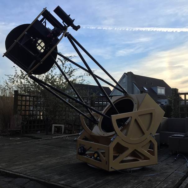
In 2010 I started building my own 24� f3.7 truss Dobson. Two years later this
was the result:
If you
like to know how it was build, please have a visit at this website:
24" f3.7 truss Dobson
I soon
realized a GoTo for this big Dobson was necessary.
Not because I couldn�t find the objects by hand but to maximize the little time
I have under dark and pristine nights. I saw numerous Dobsons
equipped with a fully operational GoTo system build
in. They all showed me the same, protruding servomotors, electric wires,
encoders, large 12V batteries.
And yes they all work as advertised. But I didn�t want my footprint of the 24�
Dobson any larger, and the GoTo system had to be
almost invisible as you looked at the Dobson.
I had to do better��
The azimuth drive
I started
with the less complicated azimuth drive. I had the idea to use toothed belts
and pulleys as they are easy to install.
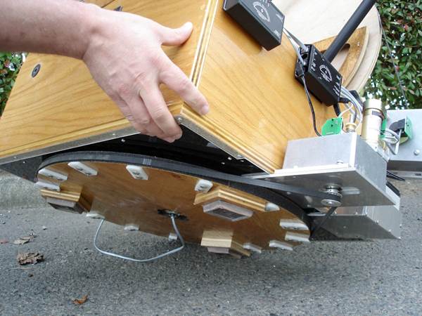
In designs of others the timing belt is loose around the groundboard
and friction between the belt and groundboard is
needed to pull the rockerbox around.
The
problems with this design are:
�
As
you can see in the picture above the belt has to be supported by the white
blocks , otherwise the belt drops to the floor.
�
The
servomotor is attached on the outside of the rockerbox
and makes the overall footprint of the Dobson larger.
�
You
have a chance of slippage. Slippage is not a problem if you install encoders on
the axis, but I don�t want extra encoders, just the encoders on the servomotors
must be enough.
In my
design the timing belt is glued around the circumference
of the groundboard and together with a pulley acts as
a large gearbox.
The problems with this design are:
�
The
circumference of the groundboard has to be as perfect
as possible.
�
It
is best the pivot point in the groundboard has no
slack.
The drawing board
Dimensions
in mm

Bill of Material
1.
Timing
belt 2535-T5-10, length 2535mm, pitch 5mm, 507 teeth, material polyurethane
2.
Pulley
30-T5-10F, pitch 5mm, 30 teeth, material aluminum
3.
Worm
Gear Speed Reducer, type A 2B 7-H480, 1 to 48 reduction
4.
Spindle,
diameter �16mm, length 114mm, material RVS 304
5.
Servomotor,
brand Pittman, type GM8224D309-R1
6.
Shaft coupling, material aluminum
7.
Needle
bearings, type NK 5/12 TN, inside diameter � 5mm, outside diameter � 10mm,
width 12mm
8.
Dowel
pins � 5 m6, length 24mm
9.
Heavy
duty hose clamp
How it is done
Preassembly of the servomotor
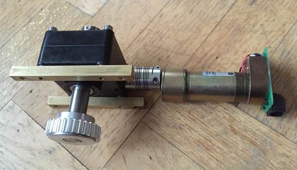
Pictured
above the preassembled servomotor and 30 teeth pulley. The worm speed reducer
in between has a 1 to 48 reduction.
To install the preassembled unit in the rockerbox I
used� two 10mm squared messing rods.
Grinding the groundboard
In my
design the groundboard has to be as round as possible
also the pivot bolt has to be without slack. I�m glad I installed the Astrosystems pivot bolt when I made the 24� Dobson. This
pivot bolt is free of slack. To get a round groundboard
I grinded the circumference with a Bosch PVS 300 AE sander. The sander is
attached to the rockerbox with a screw clamp, and by
turning the groundboard around you can get a perfect
round groundboard easily.
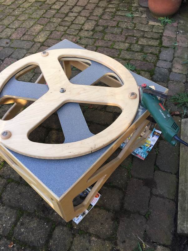
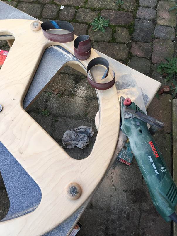
It took
me three sanding belts before all uneven spots were gone and the diameter was
big enough for an endless timing belt with a pitch of 5mm.
Lessons
learned:
�
When
I measured the groundboard it was already a bit too
small in diameter. I realized when I stopped grinding at that moment the belt
should be a bit loose around the groundboard. I
didn�t see it as a problem. Later I did regret my decision and wished I took
the time to grind the groundboard to a better suited
diameter (one tooth less).�
�
Grind
first and order a suited belt later. I did the other way round and had to order
again because the first had the wrong circumference.
Assembly of the roller bearings on the groundboard
To turn a
Dobson by hand it is common to use Teflon on Formica for the azimuth bearing.
To turn the Dobson with a small servomotor the torque needed would be too much.
Instead of Teflon, roller bearings are preferred.
I used six small needle bearings with an inside diameter of 5mm. I attached
these bearings on � 5mm dowel pins. In the groundboard
I made � 16mm chambers for the bearings with a hand drill. With a router I made
the little grooves for the ends of the dowel pins.
Gluing the toothed belt around the groundboard
The
diameter of the groundboard was a little too small,
and as a result the toothed belt was a little loose around the groundboard. To compensate I used polyurethane glue to
attach the timing belt around the groundboard.
Polyurethane glue fills the gaps and I hoped that the glue evenly expanded
around the circumference of the groundboard.
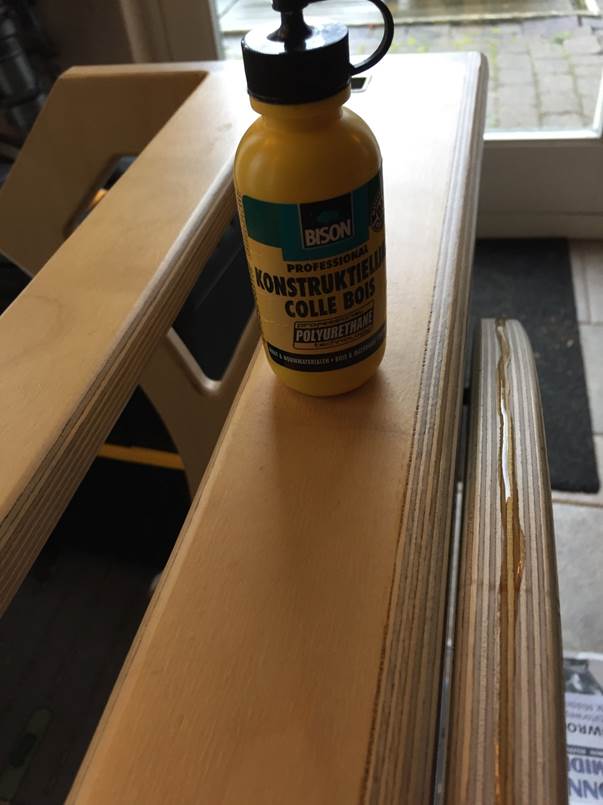
The end
result is not perfect, but still good enough.
Assembly of the pulley and servomotor
Before
drilling the holes I had to make sure I had the good position for the pulley.
Above you
can see the M6 inserts in the bottom of the rockerbox
for connecting the servomotor and pulley. In the big hole in between you can
see the toothed belt around the groundboard.
In the
picture above you can see the end result of the azimuth drive.
The gearbox is bolted to the rockerbox with little
RVS M6 bolts. The servomotor is attached to the rockerbox
with a heavy duty hose clamp.
The power supply
In my
goal to have as little cables around the telescope as possible I had to find a
solution for a suitable power supply. The SiTech
servo system runs on 12 to 24 volt DC. The servomotors are rated 19 volt DC.
I�m not exactly an electrician by profession and asked others about their
opinions.
After searching the web for a power supply that could deliver 18 volt, Henk
came up with the idea to use a 18V Li-ion battery as the power source for the
servo system. I already had a cordless Li-ion Makita Flashlight laying around
which could be adapted as a holder for the battery. With a handsaw I removed
the battery holder from the flashlight and installed the battery holder on the rockerbox.
But a question arose, could the servo system run a complete night on one 18V
4Ah Li-ion battery?
I didn�t took the risk and placed two battery holders in parallel. When the
servos are running on one battery, I have a second battery on the battery
charger. When the first battery runs low on juice, I place the full battery in
the second holder and remove the (nearly) empty battery without losing power to
the servo system.
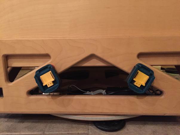
And yes I�m a sucker
for symmetry!
Testing the azimuth drive
With a
working power supply I could test the azimuth drive.
The first test was not too bad, the tracking speed was OK, but the movement was
a bit jerky. After a lot of searching and time I found the problems. Some of
the needle bearings pushed against the sides of the chambers in the groundboard. I resolved this problem by cutting 2x6 pieces
sleeves from old Festo � 8mm PE tubing and placed
them on the ends of the dowel pins.
Also a gain setting in the SiTech software was wrong.
After these small changes the jerky movement was gone. The azimuth drive draws
1.5 Amps, which is not too bad.
The altitude drive
After the
positive test with the azimuth drive I was confident enough to start with the
much more complicated altitude drive.
I didn�t want a servomotor hanging on the outside of the rockerbox.
I wanted to try to mount the servomotor inside
the mirrorbox with the drive wheels running over
the radius of the rockerbox, something that was done
never before.
The drawing board
In height adjustable roller bearings

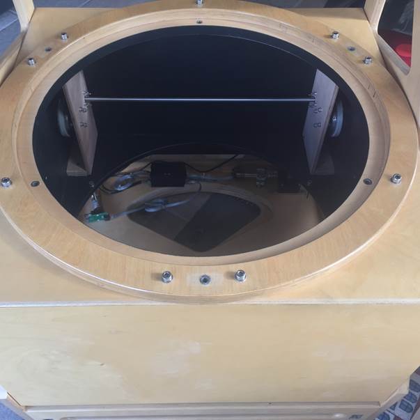
View inside the mirrorbox (topview)
Dimensions
in mm

Drive wheel inside the mirrorbox (side view)
Dimensions
in mm

View inside the mirrorbox (front view)
Dimensions
in mm

Bill of Material
1.
4x
Roller bearings, Abec 9, outside diameter � 20mm,
inside diameter � 8mm, width 7mm
2.
4x
Aluminum U-profile, 20x20x3mm, length 70mm
3.
4x
Aluminum bar, 25x20mm, length 30mm
4.
2x
Timing belt 610-T5-10, length 610mm, pitch 5mm, 122 teeth, material
polyurethane
5.
2x
Timing belt 360-T5 10, length 360mm, pitch 5mm, 72 teeth, material polyurethane
6.
2x
Pulley 30-T5-10F, pitch 5mm, 30 teeth, material aluminum
7.
2x
Pulley 60-T5-10, pitch 5mm, 30 teeth, material aluminum
8.
2x
Pulley 20-T5-10F, pitch 5mm, 30 teeth, material aluminum
9.
Worm
Gear Speed Reducer, type A 2B 7-H400, 1 to 40 reduction
10.
2x
Spindle, diameter � 16mm, length 81mm, material RVS 304
11.
Spindle,
diameter � 12mm, length 700mm, material RVS 304
12.
4x
Igubal flange bearing, EFSM-16
13.
2x
Igubal flange bearing, EFSM-12
14.
Servomotor,
brand Pittman, type GM8224D309-R1
15.
Shaft coupling, material aluminum
16.
Heavy
duty hose clamp
How it is done
Altitude roller bearing
To turn a
Dobson by hand it is common to use Teflon on Formica for the altitude bearing.
To turn the Dobson with a small servomotor the torque needed would be too much.
Instead of Teflon, roller bearings are preferred.
I had a hard time figuring out where to put these bearings, and how to attach
them on the rockerbox.
Luckily I made the wooden altitude bearing sectors a bit bigger than the usual
180 degrees, which gave me the opportunity to mount the roller bearings at the
exact end of the sector radius.
I used four Abec 9 roller bearings with an outside
diameter of 20mm and a width of 7mm. I used aluminum U-profile and aluminum bar
to make them adjustable in height.
The picture below explains it better:
I used
messing M6 inserts and RVS M6 bolts for fixing the bearing support to the rockerbox.
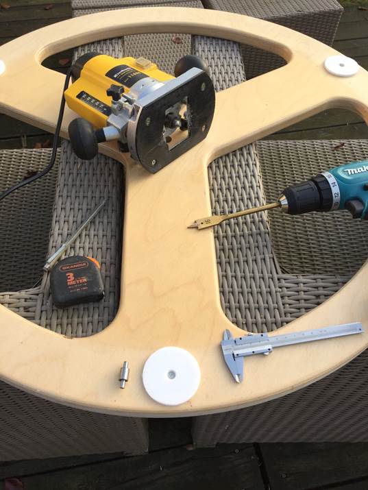
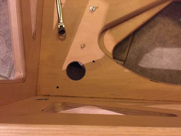
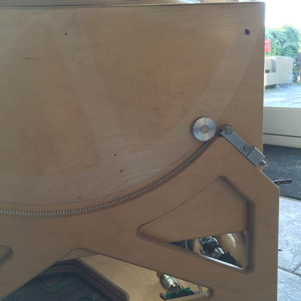
Measuring the place for the drive wheel inside
the altitude bearing sector
In my
design the place for both drive wheels had to be exact. And to make it even
worse, I wanted the drive wheels inside the wooden altitude sector, so they
would not be visible if you look from outside.
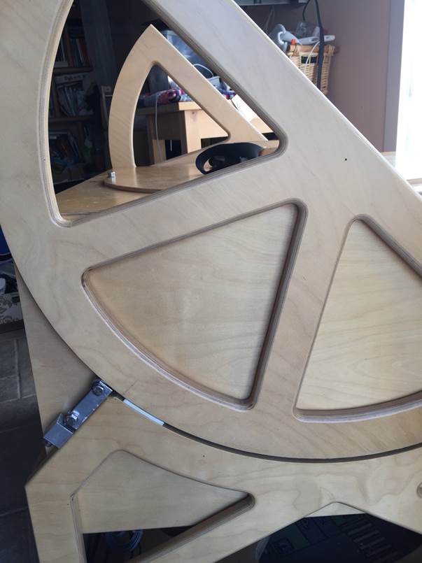
Just
barely visible in the picture above, the small line and point where a little centerhole will be drilled for the drive wheel.
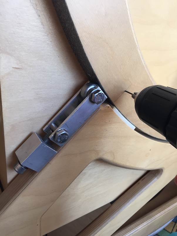
Drilling
a small centerhole for the drive wheel. The little
hole will be barely visible and is the marker for the drilled chamber for the
hidden drive wheel.
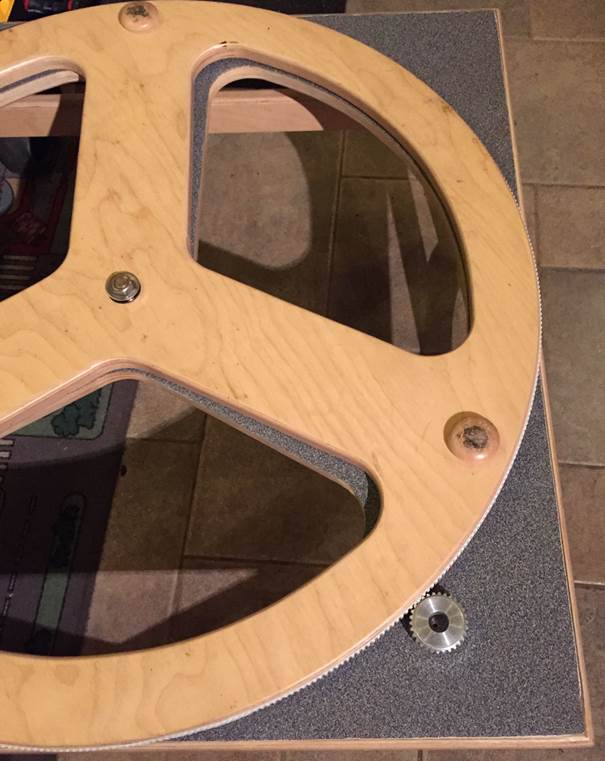
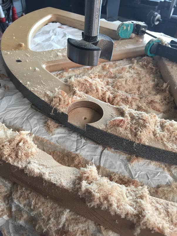
Drilling the chamber for the drive wheel
To drill
the chamber for the drive wheel in the altitude bearing sectors I had to buy a
special forstner drill bit with a diameter of 50mm.
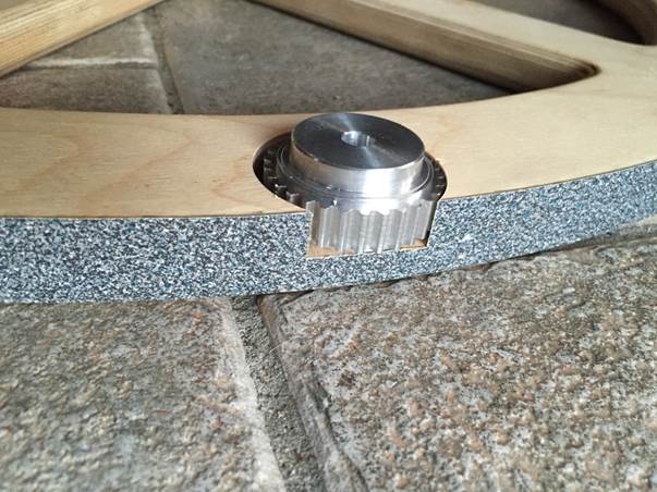
In the
picture above you can see how the drive wheel is placed in the altitude bearing
sector.
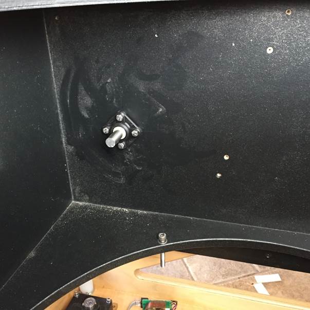
Measuring the place for the drive wheel on the mirrorbox
In the
picture above you can see the contours of the altitude bearing sector on the mirrorbox. I had to adjust the balance point of the Dobson
for the added weight of the gear train and servomotor inside the mirrorbox. In the meantime I glued the timing belt inside
the radius of the rockerbox.
The drive wheel is placed on the timing belt to drill a hole in the mirrorbox for the spindle.
Installing the gear train
The hole
is drilled for the spindle and the flange bearing is attached to the inside of
the mirrorbox with four messing M6 inserts and RVS M6
bolts.
Assembly
of the rest of the gear train.
I had to make wooden supports for the flange bearings.
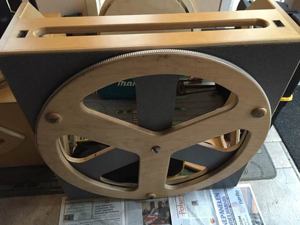
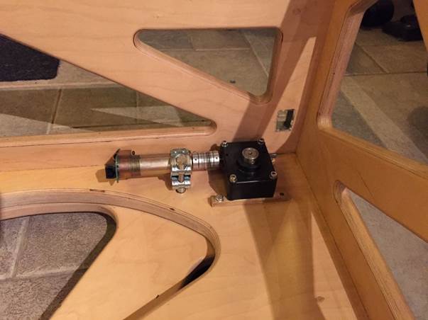
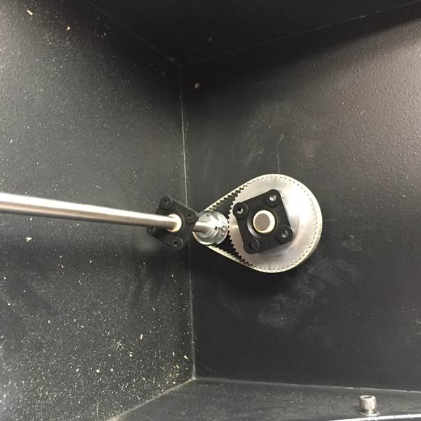
Installing the worm gear reductor and servomotor
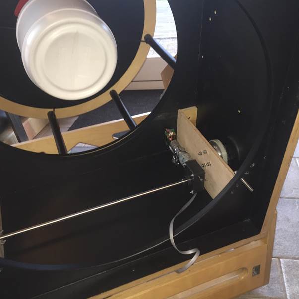
Above a
view at the gear train from behind. The worm gear reductor
and the servomotor are installed in the mirrorbox and
ready for a test in this mirrorless and trussless setup. In order to get a reasonable balance the
secondary case is directly bolted to the mirrorbox.
Finished
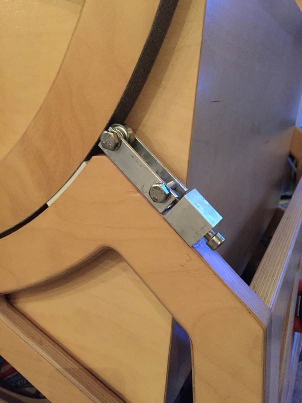
The drive wheel as seen from the outside
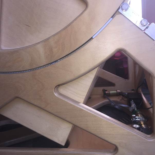
If you
look closely you can see the drive wheel between the altitude bearing sector
and the radius of the rockerbox.
Ready to Roll

I had my
first test on march 7, 2015 with the 24� f3.7 Dobson with the Encased GoTo. The electronics are barely visible and for the rest
the Dobson looks like it is still hand driven. No motors and encoders on the
outside of the Dobson, just one wire for a connection with the ArgoNavis unit or for a connection to the PC.
The test went better than expected. No corrections had to be made to the
altitude drive.
The tracking at 180x was smooth. I had Jupiter in the eyepiece for an extended
amount of time.
I used a 2x Powermate with a Denk
II binoviewer, a 2x Powermate
with a turret and four orthos, a ParaCorr
with a Pentax XW14. All combos could easily be exchanged without any balance
problems.
The servomotor for the altitude motion runs at about 0.7 Amps without any
noticeable extra heat, which was a concern when I started this project.
Credits
A project
of this size is not possible with the help of others.
I especially would like to thank the following persons:
�
Cyrille Thieullet, Astromist
�
Henk
Prein
�
Gary
Myers, StellarCAT
And I got
a lot of help from the many persons at these forums:
�
The
SiTechservo group at Yahoo! Groups
�
The
Dutch Astroforum