|
| |
|
| |
|
After having built four versions of composite epoxy/fiber Dobsons, I found out a shape and technical principles which happened to suit me. They are described in this Dobson 465 topic http://www.astrosurf.com/altaz/465_e.htm .
I wanted to go a step further : getting more photons without losing the keystone of my project. That means that I had to manage to build, carry and do the setting ALL BY MYSELF.
I soon abandonned the idea of a 600 because of the minor improvement in quality compared to the complexity of the shaping and manipulation of the mirror to which you can add the difficulty of setting the completed scope right. The only solution I could figure out was to double the number of mirrors. I had to enter the Bino dimension.
Conditions for the binoscope
1 You need two mirrors that have the same diameter and very close or identical focals. A 5/1000 tolerance is OK, beyond that, youÆre sure to get a headache because your brain wonÆt be able to deal with the two different images received.
2 The focusing of each ocular should be set independently as well as the distance between them so that different observers can watch without being disturbed. ThatÆs what is called the ōinterpupillary distanceö or IDP, generally ranging between 55mm for a child and 70mm for an adult.
3 It has to be possible to set each primary mirror independently in X and Y while watching through oculars to make the ōfusionö of the two distinct images possible.
4 At last, it is necessary to conceive and realize a dismountable cell that has to be strong, rigid because it will hold two mirrors and two secondary/tertiary/ocular blocks. This cell also has to be light enough.
Mirrors I already owned a 460 mirror and the tools I had used to shape it. So I ordered a second pre cut blank (f/d 3.9) in BVC at ASMÆs (has become AJÆS in Canada http://www.ajstelescopeworkshop.ca/ . Although this material is not unanimously acclaimed I still use it for its ease of work and for its price, cheaper (including delivery) than any european blank. I was not patient enough to do a precise control at the beginning of the polishing and the finished mirrorÆs focal is not exactly the same as the first oneÆs focal, 8mm out of 1800 so it is less than 5/1000 and...it works perfectly!
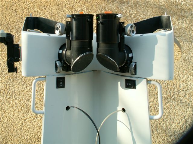
Head It is made of secondary mirrors/tertiary mirrors/ocular holders
Surfing on Dave MorhouseÆs excellent site http://www.binoscope.co.nz/ ( Morhouse being the actual ōbino guruö) or on the Benewt forum http://groups.yahoo.com/group/binewt/ youÆll see that the most frequent response to the problem of the IPD adjustment is the crafting of rotative cages allowing oculars/secondary mirrors/tertiary mirrors blocks to move independently. Despite the fact that this solution did not seem to suit my design, I felt it was too much work only to make each ocular move on a 7.5mm range (half the max difference between 55 and 70mm). To my knowledge, JMI http://www.jimsmobile.com/ make binos on which IPD and focus adjustments are part of the same whole. Having seen no photo, I imagined my own system from two 2 inches ocular holders for each block.
I kept the mobile part and I trimmed the cylinders as much as I could, they are assembled on a welded T tube containing the tertiary mirror and I could fix the second ocular holder used for the focal adjustment thanks to an adaptation piece.
The first focuser is fixed as on a normal dobson. It is used for the IPD adjustment. The second one is fixed on the other end of the T and it is used for the focal adjustment. Of course there are limitations. I get 22mm of total adjustment; 7 for the IPD , 15 for the focal.
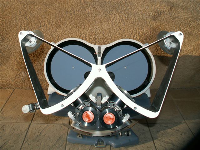
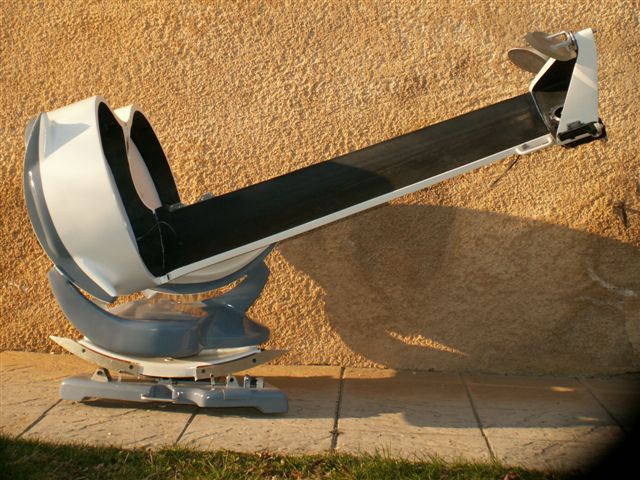
The basic principle of this bino is the union of two 460 monos, hence itÆs general design, particularly the one of itÆs head illustrated by this photo.
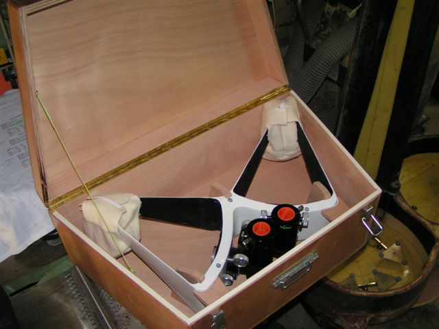
This head can be taken away and carried in a box. The system is reliable and trusty, no need to go through the whole adjustment process each time I set everything up.
Primary mirrors adjustments
Barrells have 18 floating points and their height can be adjusted via three screws. For each mirror, there are two normal hand screws allowing to adjust the collimation by screwing/unscrewing them together or independently. The third screw is linked to a small electric engine through a set of plastic gear-wheels and you can command it from the top of the bino during observation to make the images blend perfectly. .
Collimation adjustment is thus made in two steps, at first in a classic way but using only two screws for one mirror. Then by aiming at a star and using the two switches that command the engine to make the two images blend and obtain a perfect binocular vision. It is to be noticed that the original collimation is slightly modified by the second operation but it only ranges on less than a quarter of a turn, which means only a few fractions of millimeters in height and it is hardly noticeable with the control laser.
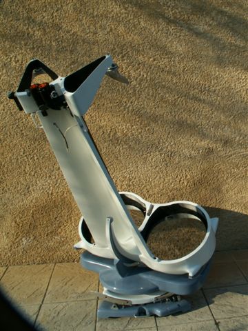
The cell
It comprises a three points rocker, a double mirror box and a ½ wing ╗ holding the head. The whole thing is built following the principles explained in the article about the 465 on this site. It is made of polyurethane kernels cut up with hot wire, stuck and put into shape. Then the whole is covered with several layers of fibreglass fabric and epoxy resin with carbon reinforcements where needed because of hard constraints. The bino lies on an equatorial table and the guidance is assured by an Argo Navis set close to the observation head.
The three points rocker has nothing particular to be told about except for a natural tendency to get itself crosswise because the guiding points are quite far apart. This problem was solved by making steps into 10mm teflon and adjusting them as precisely as possible. I used this system to gain width but I think the usual two sectors/four steps system must be more reliable.
The mirrors box holds the three guiding cushions and the adjustment screw of the 18 points barrel. It was conceived to make the two mirrors as close as possible one from the other depending on the constraints due to the presence of the observer and the orientation of the ocular holders. These datas are calculated by the excellent software developped by Eric Royer, forerunner in the bino field in France. http://astrosurf.com/eroyer/BinewtDesigner/Binewt.htm
The double wing.
Though it was part of the mirror box on the 465, I had to make it dismountable on the bino because of transport problems. Thankfully, its special shape (two long tiles welded together) makes it rigid and easy to fix to the mirror box with three bolts. It has three stems on its top to fix the head in a rigid and trusty way. Wiring has been incorporated to enable the control of the engines and to allow the Argo Navis cables to go through.
The whole bino weights 45 kg, its heaviest elements being the mirrors (14kg each). It takes about 20 minutes to get into action including fusion adjustment. Binocular vision allows a comfortable and ōnaturalö observation which is well worth the time and work spent on the making of this instrument. This article is meant to be concise and brief, those who are interested can join me for further information.
| |
|
| |