|
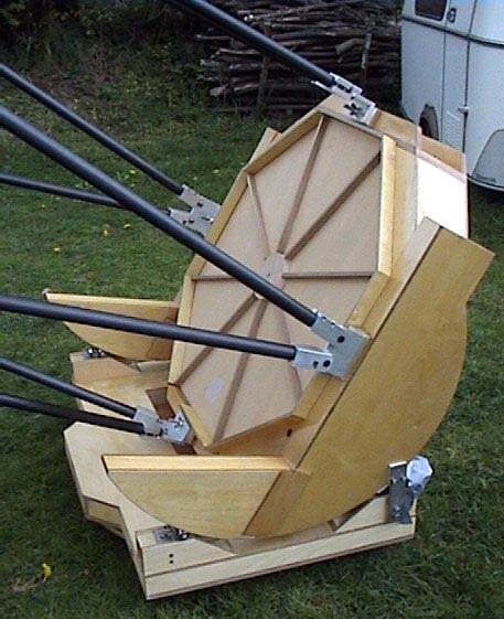
The mirror cell
The mirror cell is the first part I made.
An astatic mirror cell seems to be complex but I've found that not to be
true. The 22" cell was a good test to be more familiarized with
this system and while making it, I noticed that the tolerances of
manufacture were well within the range of an ATM. This time I choose an
astatic cell made with chrysocal blades. It's a little different system
from the classical astatic mirror cell
|
 |
| It's
very powerful and minimizes the problem of mirror flexure. However,
pushed by the desire of experimentation, I made a mistake: the levers
were too long. I have made new and stronger levers and now it's
much better. These new levers allow a more precise adjustment. First I
indeed to choose a ratio close to the 1:20 that theory says will
function but this gave many problems. This failed in practice because
the influence of a very light counterweight (120 gr.) was weak compared
to the mass of the axel that supports it. The new levers have a width of
4.7" compared to the former 2.4" in the first version. The new
levers resistance to possible deformations is much better. The supports
are composed of 9 " T " shapes. These " T's "
are made with welded pieces of steel. They replaced perfectly the
traditional triangles while offering a resistance quite higher than
typical aluminum triangles. Combining an iron "L" shape and
"U" shape makes them possible. Their rigidity is excellent.
Six of them have an astatic lever and the other 3 are on a fixed point (floating
of course). The principal piece of the cell is made using
two thicknesses of 3/8" Baltic Birch. The joining was somewhat
delicate because of an insufficient number of clamps and no screws to
join both plates. This caused one sheet to slip by about
1/16". This was corrected by careful sanding. Six reinforcements
were made using 3/4" plywood that were glued together and then
screwed. This reinforcement is joined also by two aluminum triangles
that connect the reinforcements of the lower part of the cell. In order
to further increase rigidity, all around the edge of the cell, on both
sides are glued and screwed an "L" shaped aluminum angle. The
mirror cell is "connected" to the mirror box thanks to 3
square aluminum shaped tubes of generous section, about 2.5". These
sections will receive a stainless reinforcement, 3/16" thick. They
are glued and screwed under the cell, at 120° and take part in its
rigidity. A structure welded out of steel can offer the same performance
while being easier to realize but as I like working with wood, I wanted
to try to use it as much as possible. The weights of the cell
components are: Triangles :
10 lbs Structure : 24 lbs Levers :
2 lbs
Counterweights : 11lbs
The new
levers have larger counterweight but that didn't give any problems because the
mirror box was lighter than expected.

Lateral support
are piano wire with a diameter of 2 mm, they are placed at 120° . A small
pieces parts have been specially made for that purpose. I must keep
testing but currently it seems to be good. Those supports are on mirror
box in order to minimise flexion. At that place wall thickness is about
huge because collimation threaded rods go throw them.
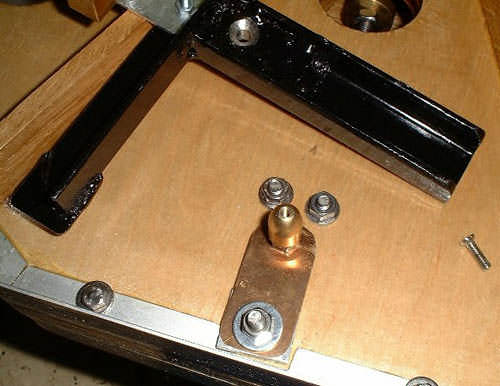
During transport, the telescope is
tighten on the trailer. So, in case of a crash, the base/fork/mirror box
will not move a lot. The mirror, free of movement might go up quite
violently. In order to "limit" as much as possible the possible
damage, I try to avoid as much as possible a instant stop when the mirror
hit the retention clips (5 mm thick stainless steel with a thick foam
under them). I’m sure a strong crash will destroy everything but in case
of light to average crash, it may be safer for the glass. In a classical
system, the only choc absorber is the thin layer of foam under the clip.


For this cell I have made a second
protection. In case of a strong crash, the retention clip rotate slightly
along a axe a long rod go to crash in a second layer of thick foam.
Pictures are better to explain the system. The rotation axe is tighten but
there is only one screw, it can rotate. I hope this will avoid some
possible damage. Also, in order to try to limit damage, the piano wire can
be remove and replace by thick foam. It’s safer to avoid as much as
possible a contact between metal part and the glass.
The collimation is achieve with 3
threaded rods of ľ inc. The 3 screw have a small motor that is connected
to a hand pad, so it’s possible to tune the collimation at the eyepiece
anytime you want. Special thanks to Francis Tisserant for is help ! The
box he made for me can also "drive" 3 fans with variable speed (two
small fans with a variable speed adjustment and a big fan with a separate
adjustment). I haven’t test them yet.

|
|
The mirror box
It is of octagonal shape for reasons of size,
rigidity and personal taste. It is a laminated composite of Birch and
extruded polystyrene foam. The plywood thickness is 3/8 " and the
foam is 2" thick for the two big lateral panels of the mirror
box. Some of the panels are reinforced with 1/2" ordinary plywood.
The connections between these plates are made with a composite of
3/4" wood with foam. Their width is of 3" thick. These
pieces are very thick because they must support the collimation screws,
which are 3/4 " thick. This octagonal shape was no easy thing to
make to make because of all 45-degree angle cuts. Compared to the
22", this meant much more work. Because of its shape using the
45° cuts these joints were also more delicate because to have a good
pressure to clamp all in place it was necessary to have parallel
guides to secure everything while the glue dried.

The
total mass of the mirror box (only parts out of wood) is 35 lbs.
Rigidity is excellent In order to minimize its height during storage
and transport, I have thought make the bearing split into two parts.
It's possible to reassemble parts to observe but the problem is a
possible lack of rigidity. I preferred to join all parts. In order to
reinforce the assembly, some small pieces of wood were added on the
two faces of the "bearing" and act as straps. During the
assembly, it appears that the "bearing" had a different
thickness than the lateral panels of the scope. This was because the
foam didn't always have the same thickness. A sanding machine is then
an invaluable tool. The assembly of the panels was facilitated by the
use of screws. The clamps cannot always do everything. The precision
of the unit is, I hope, correct because as it turned out, it is
approximately 1/32" to 3/32 " off compared to the ideal
dimensions. For 1000 mm, that gives 1003 mm length and on the others
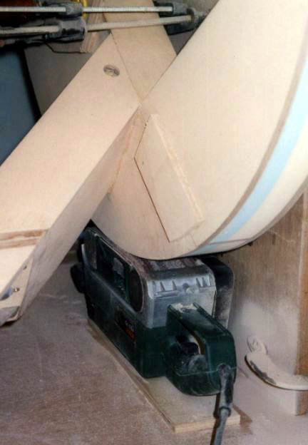
faces of 999mm a 1001 mm. That should not be too much of a problem. In
order to smooth the bearing, I used the same method that one use to
make equatorial forms, rotation of the parts on a grinder, which is
fixed. With a design like that of the 22" or this 32", the
problem it is that there is no actual of the center of the bearing.
Thus I had to make an assembly in order to grind those bearings. The
axis used was an aluminum bar 1" in diameter. It will latter be
used for the axel of the telescope wheels. The operation is a little
delicate and it is necessary to take care not to remove too much all
at once. The grinder is placed on an increasingly thicker plywood
plate in order to remove the material gradually. It is a little
delicate and should be taken slowly. If the grinder hangs too much, it
digs in a begins to turn the mirror box. The result of this method is
astonishing. The surfaces that were rather irregular are now perfect.
It should be hoped that the axis did not move (but it does not seem
to) during all the operation but if not, the form obtained is still a
beautiful disk. Having a smooth regular surface, a 1 mm thin stainless
section, has been glued in order to reinforce this surface and give a
good surface for ball bearing. Four layer of polyurethane coating have
been apply on the wood to protect it.
 La batterie de serre joints utilisés pour le collage.
 |
|
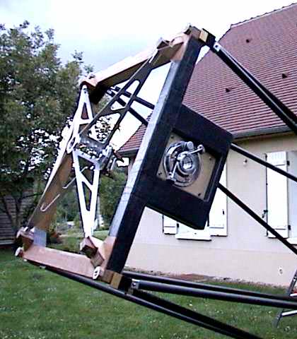
The truss tubes
I have tried to maximize the base of the
triangles formed by the truss tubes. As the shape of the box with
mirror is octagonal, the serrurier truss is inverted with regard to
the classic model, which implies a cage with a square shape. It is
certainly possible to realize a classic shape, even to use only 6
tubes instead of 8, but if we wish to maximize the strength of the
structure, it is necessary to maximize the width of the
"base" of the triangle. The square cage allows me to obtain
this most important rule.
The
choice of truss tubes was an especially tough one. Using a spreadsheet
article that appeared in an issue of Sky and Telescope by Roy
Diffrient, it was easier to test various combinations. The aluminum
tubes are usually used. Considering the size of this scope, they are
unfortunately too heavy to use, difficult to find, and expensive. Due
to the short focal length of the mirror, F/3.75, it was necessary to
look for something stiffer and of a lighter material. There is not a
great deal of material available that can answer these two criteria.
Using carbon fiber tubes seems to be the ideal combination of weight
and rigidity. The price is certainly higher compared to using aluminum
tubes. Their "exotic" size that is offered is still quite
close to standard aluminum tubes. There are various types carbon
fibers. Not being expert on the subject, I simply noticed that the
carbon fiber named "pultrusion" was the best adapted to a
serrurier truss by being almost twice as stiff as the classical fiber.
The classical carbon fiber certainly is interesting, but its strength
is much lower.
|
Material |
Mass for 1 liter |
Young Modulus |
|
Steel |
7,8 kg |
210 |
|
Aluminium |
2,7 kg |
70 |
|
Classical Carbon fiber |
1,5 kg |
70 |
|
Pultruded Carbon fiber |
1,5kg |
130 |
This difference between both types of
carbon is very important because the module of Young, an indicator of
rigidity is almost twice
superior. ...Unfortunately, there are only a few companies that make such
a product. The Structil Company, based in the South of Paris, makes a good
product. I bought 8 ft lengths in a diameter of 1.2-inches and .078"
wall thickness. The weight of the 8 tubes is about 12.6 lbs. The cutting
of the tubes has been done with a disk. but it seems that it is necessary
to take a few precautions: Wear gloves, a dust mask, and glasses and clean
up as much as possible the very irritating dust. I will try to cut that
tube using a Dremel system


|
|
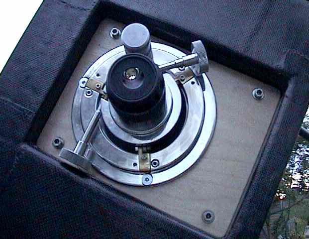
Secondary cage
The cage is square. The foam is 2.4 inch
thick and the plywood is 1/8 inch by 3.1 inch wide. The foam that is
not covered with plywood is protected with a wooden veneer 1/32"
thick. A coat of polyurethane varnish over a layer of epoxy help to
protect it from moisture. As mentioned previously, the square cage
allows, in this design, to obtain the maximum space at the base of the
truss tubes, about 40-inches and thus will obtain a maximum strength.
The weight of the cage is around 6 lbs. The spider is finished. The
aluminum blades are 2 mm in thickness. The central body raises a
problem because it is also made with aluminum and its weight was high.
This issue was corrected following a lot of machine work to lighten it
by milling away a lot of its mass. The secondary holder is a special
one, the mirror can be extracted without any tools or loss of
collimation. It’s safer to remover it during transport or set-up.
The focuser is attached on a separate panel with a foam "arch"
cover by carbon fabric and epoxy.

|
|
The base and the rocker
Its structure depends mainly on the choice of
the motorization and the form with which I will move the instrument
when is on the ground. The motorization is a delicate element. There
are several possibilities: Use a DobDriver II, Mel Bartel's system, a
ServoCat system from www.Rxdesignonline.com or an equatorial table,
or. This last solution is very pleasant to use but for an instrument
of this size, it starts to become a very big platform. The eyepiece is
already at about 9 feet at the zenith. Gary Myers’s solution (ServoCat)
has been choosen, they will be a page devoted to that subject soon.

The
goal is to integrate as much as possible the motorization so that it is
the least cumbersome possible. The base must have an accurate shape in
order to accommodate the azimuth motor, like Charles Stark did to install
his DobDriver on his obsession. The base's edge is covered with a
polyamide tape in order to offer a good "grip " to the toothed
wheel of the driving pinion. As Gary’s solution requires a low friction
movement, good quality ball bearing, like those used for roller blades,
has been chosen instead of the traditional pads of Teflon on FRP or
Formica. For a telescope used on an equatorial platform, a DobDriver II
without roboscope or a tradition ground board, the Teflon/FRP combination
is preferable because the bearings are sometimes more delicate to tune and
can require the use of brakes in order to control the quality of the
movements. I also to use bearings for the pivot but I do not know yet how.
In order to minimize the height of the instrument, the base is bored in
its center, leaving the free passage in front of the mirror when the
'scope is aimed at 45°.

The structure of the base is also in
composite of 3/8" plywood (visible panel) and 2.4-inch foam and 1/2
inch plywood for the low part of the base. Four inflatable wheels of
10-inch diameter with roller bearings are placed on a 1-inch aluminum bar.
They are removable by the use of pins. The axels of these wheels pass
through the sides of the base. At the place where these axels pass in the
fork, there is a plywood reinforcement, 3/4-inch thick. The edge of this
is 3/8" thick. Removable bars, intended to exert the push during
transportation of the instrument, will be fixed on the side of the
telescope. That also has the advantage of avoiding a possible swing of the
mirror box out of the pivots during Transport


|
|
Transport
Since I have
seen the beautiful trailer used by Patric Lequevre to transport his
18", I want to adopt this solution. The instrument being of
rather large size, approximately 40" x 40" x 120", it
is difficult to transport in one piece, so it will be dismantled for
transport. Dismantling also allows helps to reduce the size of the
trailer |
|
Optic
A 40" mirror about 2" thick
weighs around 180 lbs. This Russian 32" blank I'm using is
a thin meniscus disk, 1.6" thick. The meniscus shape allows
compensating partially for the weakness in a 1.6" thick blank of
this size. The weight saved by this shape is interesting because this
thin primary weighs only around 100 lbs. The problem of it's "convex"
back is that the contact points of the cell are more delicate to
adjust. It taked some time to tune it. The secondary mirror is 6-inch
minor axis. The FD is 3,75 and a Paracorr is used for low power view.
The secondary is a 6" model, so obstruction is around 18,7 %.
|
|
Setup
It’s a one person setup scope. First the
truss is install and a thin alu blade with Velcro glue on it keep the
space between truss element at the good distance. Then, a piece of
wood keep the scope close to an horizontal position, the cage is
installed and the blockage system is removed.

|
|
Some tuning soon
The mirror is not centered on the bearing
line (85 mm back) so the center of gravity is not at the good place. A
Tom Krakjii virtual counterweight will be added soon to avoid this
problem. Also, baffling of the secondary will be added in order to
have the best possible contrast. I don’t want use a full baffle
system to avoid wind sensitivity as much as possible. Different
solution will be tested till I find a good one. Collimation motor
currently stall but not because of the load, it’s because of too
much friction on treated rods, those friction have been removed a
other test will say if the motor are now strong enough.
|
|
First light.
First light has been tough because of bad
weather…Murphy’s law again…First, the mirror has been put in the
mirror box. It’s a 100 lbs piece of glass but thanks to the very low
profile of the box, it’s really easier to do with two people than to
put the 20" in a classical dob. After some tune of the astatic cell,
the scope has been aimed at M13, like for the 22". …Amazing !!!
pin point star cover the field of view, and even more impressive, the
mag 12 galaxy just next to M13 is now a beautiful galaxy, no longer a
faint smudge of light. M57 is also great. A thin line of different
"color" is now visible all around the classical annulus. This
one is visible on some pics as a thin red line. The central star is
visible 75 % of the time. Needless to say I’m happy !!!

|
|
|
|
 home |
|
