The electronic part of the Audine camera requires a +/-15V symmetrical power supply. Consumption is 30 mA for the positive voltage and 10 mA for the negative voltage. If possible, the peak-to-peak ripple must be lower than 5 mV. To reduce the electronic noise level, it is recommended to choose a linear type power supply instead of a switching power supply since the aim is to control sensitive electronic circuits such as the ones in a CCD camera. The required power supply can be easily built using 7815-type voltage regulators (for the positive voltage) and 7915 regulators for the negative voltage as well as a transformer, a few capacitors and rectifier diodes.
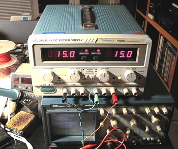
It is however easier to buy it from a shop where it will cost you less than $50 (in France). Manufacturing such a device might then be a waste of time in some instances. The AL890N power supply made by the company ELC for instance is adequate. The only problem with a low-end power supply is that it does not tell you how much current is actually used up. That is a pity because this value gives a good indication to trouble-shoot the device (to detect short circuits, wrong connections, etc). Generally, measuring a current using a VU meter or a LED display is only available on more costly power supplies ($150 and more). Note however that for a normal operation of Audine you must not use a laboratory power supply because the output voltage can be adjusted. In such a case, an incorrect setting can overload the camera and seriously damage its components.
Whatever type of power supply you choose, you must be really careful not to reverse the polarity. Before you switch on an electronic equipment, be sure the power supply wires are correctly connected.
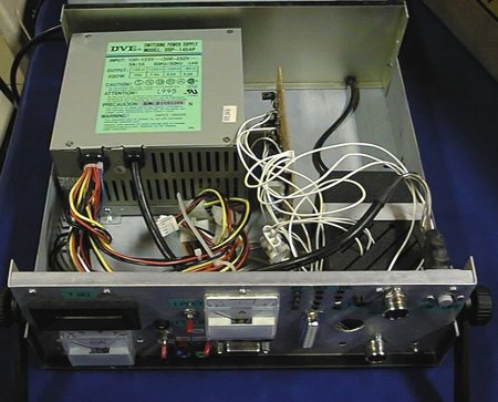
To supply the Peltier module, you need a 5V DC voltage with at least 2.6A. To generate this voltage, the best is to use a computer power supply. It is a switching power supply but that is acceptable since it is used to supply the Peltier module. It can generate a high current flow under 5V (20A for instance, ie more than is necessary). The price is very low - sometimes less than $16. It must be noted that the Audine cooling device has been designed so that such a cost-efficient power supply can be used. Another big advantage of a PC power supply is that it generates the 12V voltage required by the fan that cools the Peltier module radiator.
Be careful though with the most recent PC power supplies, in particular those
compliant with Intel ATX standard. You may have to install wires at a terminal
(simple operation) so that it actually delivers a voltage (these power supplies
can be electronically cut off). Similarly, the +12V voltage used for the camera
fan will not be generated if the power supply is incorrectly wired. For more
information about ATX power supplies, click here.
The PS/2 (or AT) power supplies are more traditional and do not pose this kind
of problems. They must therefore be the preferred choice.
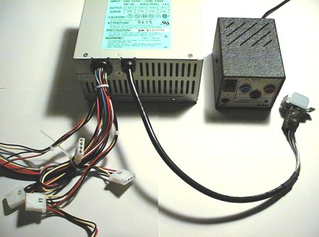

To route the Peltier voltage generated by the PC power supply to the camera, you have to make a special cable fitted at one end with a 4-contact male connector, the kind used to supply computer equipment. It is a very usual component that can be found in computer shops. This connector can be taken from a hard disk or CD-ROM extension cable.


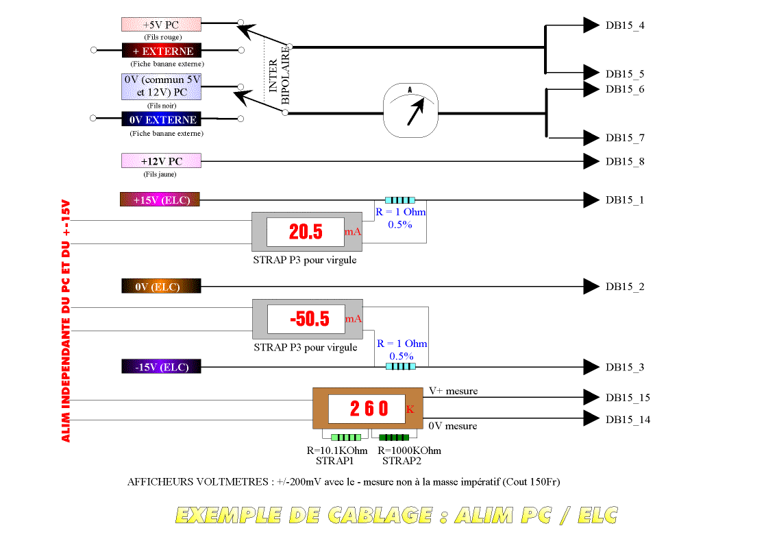
You have to complete the DB15 connector wiring. Up to now, the 1, 2, and 3 pins of the DB15 connector were respectively used by the +15V voltage, the ground and the -15V voltage to supply the electronic circuits.
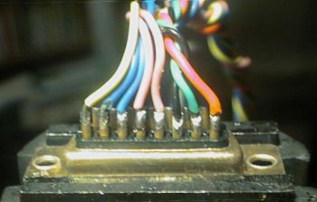
The wiring diagram of the DB15 connector is as follows:
|
|
|
|
|
|
|
|
|
|
|
|
|
|
|
|
|
|
|
|
|
|
|
|
|
|
|
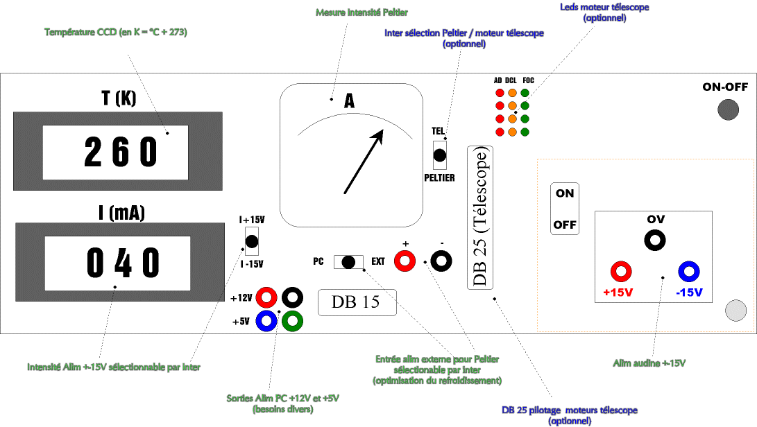
Because the current generated in the Peltier module is rather high, and in order
to limit the voltage drop in the power supply wires, the latter have been doubled
for the 5V voltage and the Peltier ground. The fan ground is the same as the
Peltier module ground. Note that the electronic ground and the Peltier ground
are completely separated. To avoid any problems, it is recommended to put all
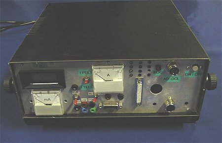
the power supply modules (+/-15V, +5V, +12V) in a single box. An Audine power
supply DB15 connector must be installed on the front face of the box so that
you do not hesitate when connecting the wires.
 |
 |
|
|
|
|