
 |
 |
 |
 |
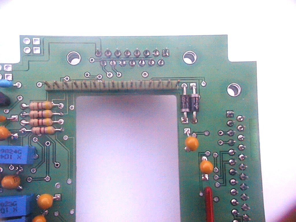
The lower board wears the circuits of interface between the PC and the power supplies. We can recognize the lower board among the two printed circuits looking at the rectangular hole that is the biggest.
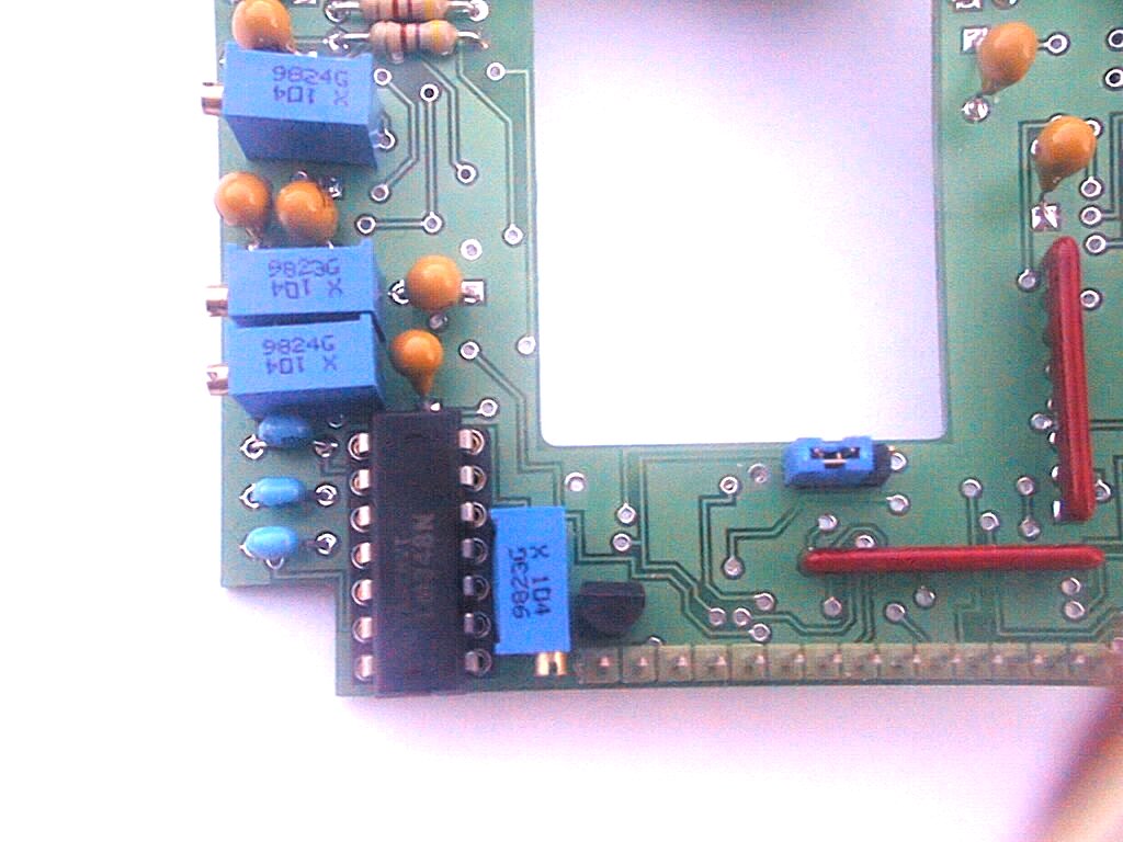
On this card, on the side of the solders, we notice 2 miniature integrated circuits. Their case (CMS type) allows reducing the overcrowding. They are 74HCT14 (Schmitt trigger) that contain 6 reversers. They transform the logic signals possibly deformed coming from the computer into signals with steep fronts.

The lower board seen on the side of the solders. Notice the two pre-wired CMS circuits. On the above CMS, leg 1 is located on the inferior row on the extreme left. On the CMS on the right, leg 1 is located on the above left row.

The first step is the realization of a power-supply wire for your camera. It is used to supply the camera (+15V,-15V and the ground). Later, the wire will be completed with the power-supply wires of the Peltier module, power-supply wires from the ventilator, wires from the thermic probe, etc. For the moment, the wiring is limited to 3 wires: a wire for the +15V, one for the -15V and a ground wire. The length of the wire will be 30 to 50 cm and the wires will be twisted.

For the camera, the three wisps are soldered to a female DB15 connector. This connector has 15 pins on 2 rows. The plan of wiring of the DB15 is the following:
Pin 1: +15V
Pin 2: 0V(ground)
Pin 3: -15V
For the power-supply, the "banana" plugs with different colors are assembled on the wires. It is recommended to respect the color codes:
The wires are denuded on a length of 2 to 3 mm on the side of the DB15 connector and on a length of 5 mm on the side of the "banana" plugs. A small vice is useful to maintain the elements to solder.


On the side of the DB15 connector:
|
|
|
|