
Final result.
 |
 |
 |
 |
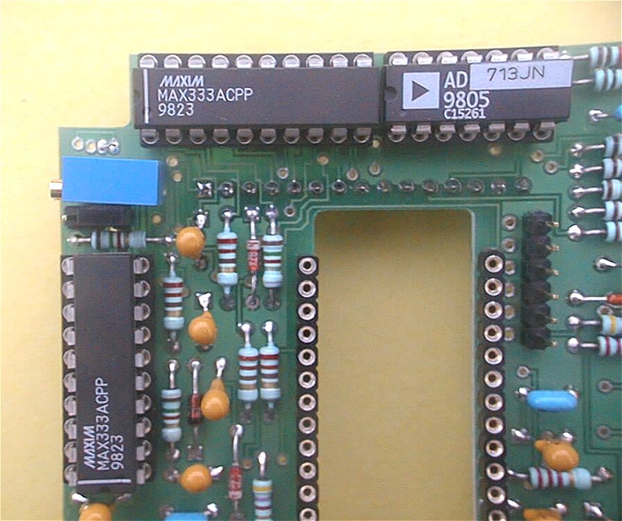
Details.
Cabling the upper board isnt more complex than cabling the inferior board. Theres just a little more components to set on the board.
As for the first board, the components are set on the ground side (the side with the silk-screen printing AUDE SUP).
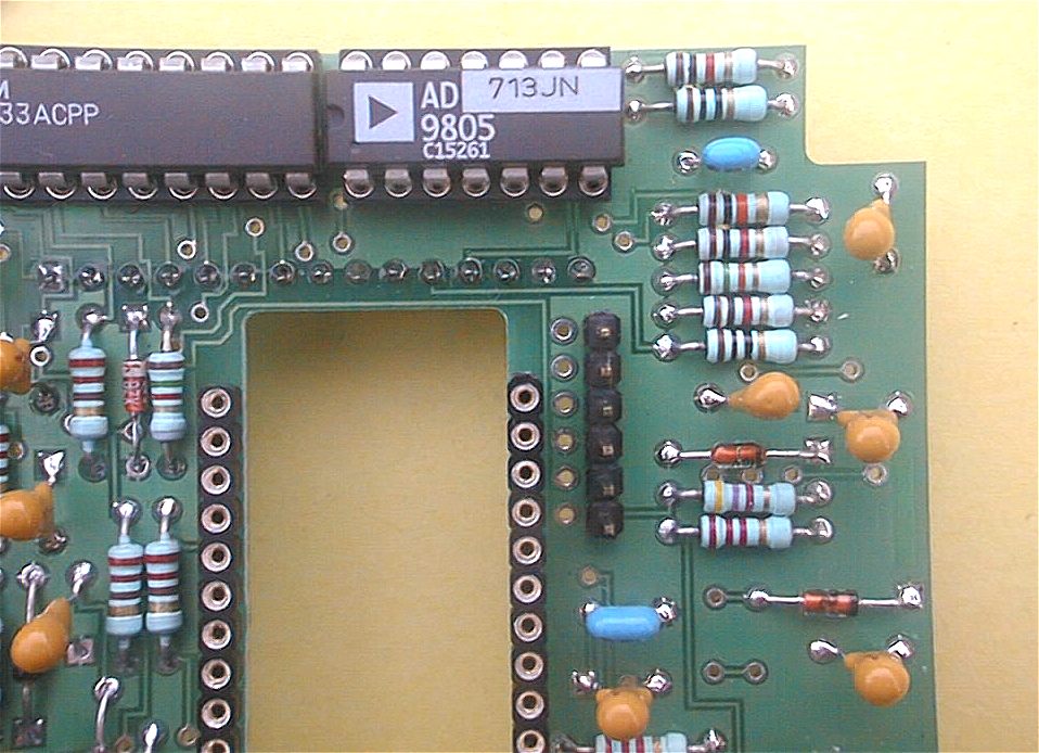
Begin by soldering the resistors R6 to R26, then the diodes D3 to D8. For those ones, take a particular care to respect the position of the line drawn on the diode, compared with the mark on the cabling plan.

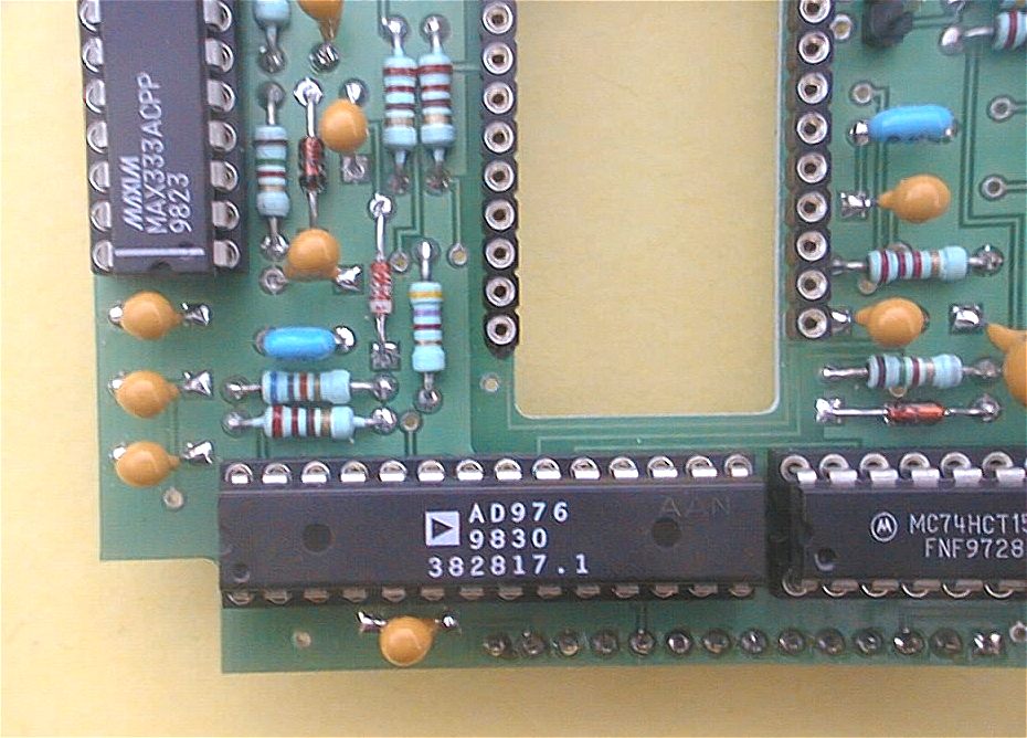
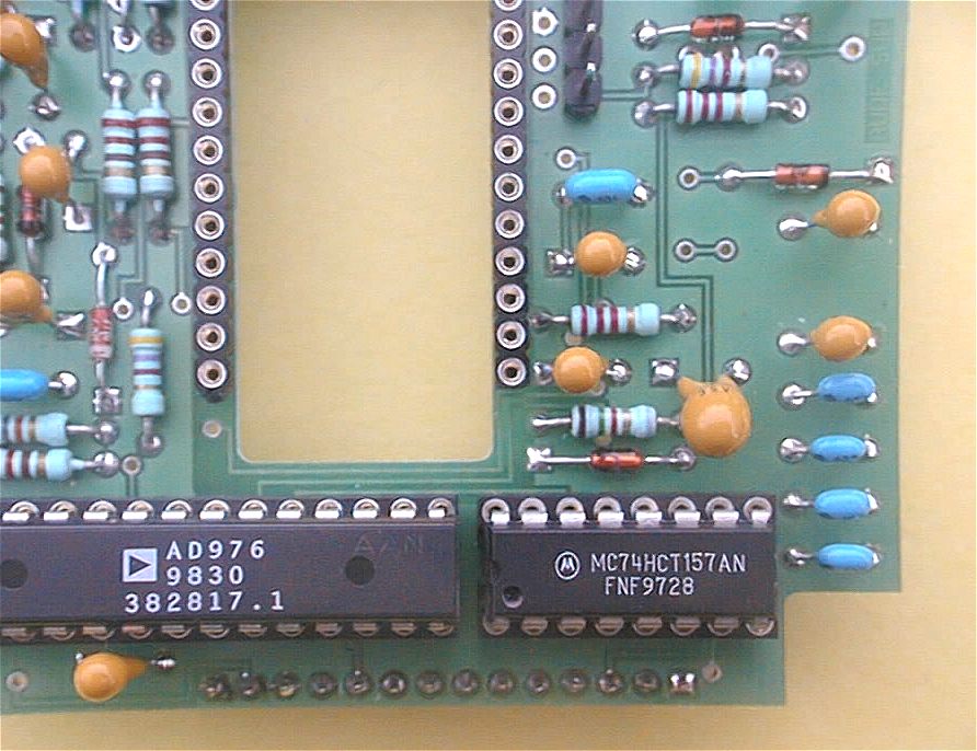
Then proceed the setting of the bars which will receive the CCD. It is a very important step that requires some precision. Indeed, if you dont set these bars correctly, the sensible area of the CCD will be inclined compared with the plan of the printed circuit boards. This inclination can cause problems to the setting of the boards in the mechanical case. Cut a 12 pins bar in the tulip ones using the wire cutters. You will need two of them to constitute the two rows necessary for the CCD plugging. Theres an important advice (as for the first board) : do not try to solder the 12 pins of a bar at the same time : begin by maintaining the bar well plated and straight with an adhesive tape, and solder only an extremity pin. Remove the tape and check if the bar is correctly set : in the wrong case, lets replace the bar by heating the tin. Solder the other 11 pins when the bar is correctly pushed in. And do the same for the second row. Another technique consists in setting the two bars simultaneously, turning the board out on the working plan, and slightly weighting on it to ensure the bars to be correctly plated. After having soldered the both extremity pins, you can adjust the placement by heating them. You can now finish the 10 other pins, and proceed the same for the next bar.

Install the capacitors C13 to C35. Be careful with the Tantalus capacitors : they are polarized so dont forget to turn them in the right sense. Think for each Tantalus drop capacitor (orange color) to examine the conformity of your work compared with the layout schema : it is better to lose few seconds here than to unsolder a component which is always laborious.

|
|
|
|