
Place the four 100K potentiometers P1, P2, P3 and P4. These potentiometers will allow regulating the amplitude of the CCD clock tensions. Lay the base of the potentiometers on the card. First, only solder one of the three pins. Then, heat the already soldered pin and at the same time, lay the potentiometer flat pressing on it. Solder then the two remaining pins. Orient the potentiometers so that the regulation screw is turned towards the exterior.
The four clock tensions regulation potentiometers are soldered. These potentiometers are multitour ones. To explore their resistance range, you must turn 10 to 20 times the small screw.
The 3.3K resistance R5 is optional. It is useful if you install, in the camera, a type LM335 thermic probe to measure the temperature of the CCD. We recommend you to wire it, even if you don't use it. It will be simpler if you decide to use this option later. After the soldering, cut the legs that stick out of the printed circuit to eliminate a short circuit with the DB25 connector you will assemble.
You are nearly over with the wiring of the inferior card. You still only have to place the male connectors CON3 and CON4, respectively of type DB15 and DB25. It's imperative that these connectors be assembled straight and correctly laid on the card to ensure a good integration of the electronic cards in the case of the camera. It's enough to fix the connectors, before soldering, with M3 screws going through the holes of the connector and of the printed circuit. Screw moderately the screws to ensure a mechanical contact between the base of the connector and the printed circuit. Be careful, the DB15 and DB25 connectors are assembled upside down with respect to the other components of the card. You will have the impression at each soldering to produce a short circuit with the ground plane. But in practice, it is not true. The printed circuits you own are of high quality. Put a moderate quantity of soldering on the legs, but make sure the electric contacts are made indeed.
Don't cut the legs of the connectors after soldering. They don't disturb the mechanical integration and they could be useful for future extensions of the camera. For example, they will help you to add a temperature probe.


Connection of the power-supply wire to the +/-15V tension source. Here a fix power-supply, from the trade, of trademark ELC (model AL890N). It is very important to respect the polarity of the wires. Traditionally, the red wire corresponds to the positive tension, the black one to the negative tension and the green one to the ground (middle point of the tensions).
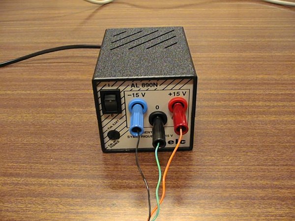
The ELC company hasn't respected this convention. The negative terminal is blue and the ground terminal is black! To comfort yourself, you can choose "banana" plug colors in agreement with those adopted by the manufacturer, like on this figure.

It's possible to use a laboratory double power-supply to produce the +/-15V symmetric tension by realizing the wiring plan of this figure. Be careful during the use of a laboratory power-supply: the tension can be easily regulated. It's very easy to apply mistakenly a surge of voltage to the camera that can lead to its definitive deterioration. Avoid, too, using different power-supply blocks for the positive and negative polarities, to link by a wire to the common point, because you will not power on simultaneously the two polarities, which is never favorable with sensitive electronic circuits.

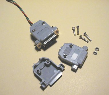
DB15 connector solders can be protected from a bad surprise, like a short circuit, with the help of a cover. On the other hand, the latter facilitates the handling of the connector and eliminates the bad reflex that consists in pulling the wires to switch off the plug of the camera.
If the polarization of the power-supply is not correct, the D1 and D2 diodes
protect the card. But the power-supply can be short-circuited and flow a strong
current. In this situation, a laboratory power-supply will stop flowing the
excessive current thanks to an integrated limitator. With an economical power-supply,
like the ELC AL890C model, you must be careful because the absence of an ammeter
doesn't allow an immediate detection of a short-circuit. In this power-supply,
the tension regulation is made through simple 7815 and 7915 integrated circuits.
In case there is a short circuit, these components will automatically stop flowing
when they become hot. The delay between the moment when the short circuit happens
and the stop of the power-supply can be of several tens of seconds. If you notice
an abnormal heating of your power-supply, rush to its stop switch. Correct the
mistake (it's usually a simple reversal of the 3 power-supply wires), wait some
minutes for the temperature to become normal again, then make a test again.
Power on the power-supply. With the negative touch point
(black color) take the ground on the free pin of the TB1 connector, as it is
shown on the image below. This pin is linked to the ground.


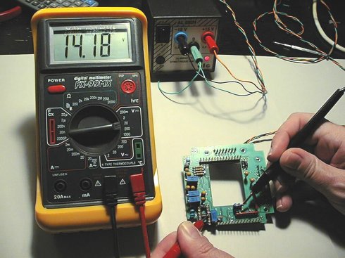
Test of pin 4 from the tulip holder of the integrated circuit U3. Here, we don't find again the +15V of the tension of the power-supply because of the drop of tension caused by the protection diode D1. Equally, a tension lower than -15V will be noticed on pin 11 of this same circuit because of diode D2 on the power-supply line. These gaps are of no importance.
|
|
|
|