REALIZATION OF THE PC/CAMERA
CABLE
Before the final test of the boards, you must make the linking cable
between the Audine camera and the PC printer port. The following figure
shows how the cable should finally look.

The ribbon cable is 3 or 4 meters long (enough for the tests) and
has DB25 plugs
The cable is ended by a DB25 plug on one extremity and by a DB25 socket
on the other one. The easiest way to make such a cable is to use a ribbon
cable and plugs to crimp. It is mandatory to use a twisted pair
cable because each wire conducting a command signal has its own ground
wire (This cable has the reference number 111-8893 at Radiospares). Thanks
to the crimping technique and by following the instructions, you will need
only few minutes to realize it.
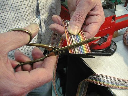
Begin by cutting the cable with good scissors, well right
and with a right angle compared with the direction of the wires. You must
cut the cable where it is not twisted. It is important to check that some
copper wires dont pass the sheath not to provoke a shortcut between two
adjacent wires.
Do not hesitate to cut again the extremity of the cable if it is
not right and precise.
The ribbon has 26 strands organized in 13 twisted pairs. Because the
connector has only 25 pins, you must eliminate a strand by separating it
from its neighbors on a length of a few centimeters. This operation
is easy thanks to the very soft plastic linking. You can begin to separate
it only with a nail.

On this photo a strand placed on one side of the cable has been
detached (it is arbitrary the gray one). Of course, you must detach the
same wire at the other extremity of the cable. You can even cut it because
it is a priori useless. We recommend to keep it if one day you want it
to conduct a signal which is not foreseen at the origin.
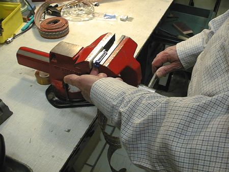
You need a good vice for the crimping operation.
You must slip the ribbon in the appropriate connector slot. At this
step, we must be OK on the cable colors code and on the numeration
of the connector pins. Locate the pin numbered 1 on the DB25 connector.
The number 1 appears on relief very close to the pin of interest. Try to
set the brown strand, located at one extremity of the cable, facing the
connector pin 1. The same strand must connect the pins of the plugs and
the sockets.

The cable must be right set before the crimping. The wires will
be in the connector internal forks axis to assure the electrical contact
after tightening. The strands mustnt get out a lot of the connector. Notice
that you mustnt tighten directly on the fore side of the connector (here
the male) because it is fragile. As it is shown on the photo, you must
put a small, old piece of printed circuit board or a wooden piece between
the jaws of the vice and the metallic part of DB25.
After having correctly placed the ribbon cable in the connector,
you must tighten the jaws of the vice. Realize this operation slowly but
do not hesitate to force until the plastic pieces are in contact. A clip
system assures the mechanical maintenance of the connector pieces.

On this photo, you can see the two contiguous parts of the
connector. At this step, the wires are really connected and you must stop
the tightening.

Set the maintenance piece given with the connector to protect the
electrical contacts. As it is shown on this photo, you must turn down the
ribbon cable on the connector and clip the maintenance piece.

To set the security piece, you must use again the vice. Force until
the piece is clipped on the connector.

The two extremities of the cable have the DB25 connector, one male
and the other female. Take care that the corresponding pins of the male
and female connectors are correctly linked. For that, use the colors of
the ribbon cable. Observe the direction of the ribbon cable compared with
the sense of the DB25 male and female on this photo : it is optimum while
plugging the connectors on the camera and on the PC (be careful : on this
photo, the security pieces are set at their place). As a precaution,
use an ohmmeter to check the electrical continuity between the two extremities
of the cable.