You are very close to powering up the CCD and taking your first image. It is important to make this image in complete darkness. It is not dangerous at all for the CCD to power it up while it is exposed to bright light. But, the most important tests should be done in almost complete darkness; after all: you will usually use your camera in these kinds of conditions if you are doing astronomical observations. The detector is extremely light sensitive; just putting it in the shadow is not sufficient. Your workspace should be quite dark and all lights should be switched off (Working at night is ideal if you don't want to be disturbed by too much daylight coming in through the curtains). Also lower the brightness of your computer monitor, if possible. We suggest using a black cloth to cover all of the electronics, this works very well.
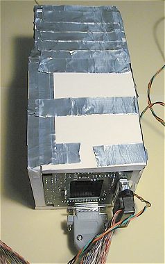
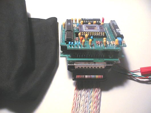 You are now ready to make your first image. The camera is connected to the PC via the flat cable. On the left you can see the black cloth used to cover the boards. During testing you should also switch the room lights off.
Check for the last time if the CCD is mounted in the right way. Start the PISCO software and connect the power supply to the electronics. Close the curtains, switch off the room lights and cover the CCD with several layers of the black cloth. Use a flashlight to find the keyboard when changing the parameters in PISCO. Set PISCO for an exposure of zero seconds in 2x2 binning mode in the Standard window. Click the GO button to start the exposure.
The next 5 or 6 seconds will probably be among the longest in your astronomical career!
After PISCO finishes reading the CCD, it will display the image automatically on your monitor. If everything is OK you will see in the histogram window, under the sliders for setting the display values, a concentration of pixels with pixel values around 2000 to 7000 (this is the offset level of your camera). Adjust the upper and lower sliders to the highest and lowest pixel value. If the image approximately resembles a uniform grey area, its BINGO, you got yourself a CCD camera!
 This is what your first CCD image should look like!
The test in complete darkness that you are going to do will show if your camera is working properly.
Note that the image is somewhat darker in the lower right corner than in the upper left corner. This difference is not due to
illumination of the CCD because it is plunged into complete darkness. What you see here is evidence for the generation of a thermal signal, or dark current, in the CCD.
The longer a packet of charges moves through the structure of the CCD, the more parasitic thermal charge it will collect. Well, the pixels in the lower right corner, are the first that are read and the ones in the upper left corner are read last.
The latter pass 5 seconds longer through the CCD than the former, this explains the non-uniformity in the image.
(remember that the CCD is not cooled during this test). Don't consider the gradient in the image a defect, but on the contrary, a sign of good health. Note again the faint vertical lines that seem to emerge from certain pixels. These are the result of the presence of hot pixels, pixels that that are affected by a dark current much higher than average. All of this will disappear when you cool the CCD.
To continue your investigation you have to make two exposures, one after the other, again in total darkness but this time in binning mode 1x1. It's best to work in console mode. To switch to console mode, right click with the mouse somewhere in the image zone and choose console. Select binning mode 1x1 and set an integration time of zero seconds (this is the lowest possible value). Start the exposure by clicking the GO button. The readout time is considerably longer this time: about 20 seconds. After digitising, save the image to disk and give it a simple name (I for example, for Image). To do this type the command SAVE I
in the console window. Start another exposure under the same conditions and save it as J. Now you are going to subtract image I from this image and add a constant of 1000 to the result. This constant prohibits pixels with a value close to zero getting a negative value, taking in account the similarity of the two subtracted images. To effectuate the subtraction of the image in memory and image I, you have to type the command SUB
I 1000 in the console window. To view the result, type the command VISU 1400 800.
The two parameters in the VISU
command are respectively the high and low thresholds for visualisation.
 The image you see now is much more uniform than the individual images.
By subtracting the two images you have eliminated their systematic defects, for example the gradient and the hot pixels. Only the noise, that is different from image to image, remains. The absence of vertical or horizontal parasitic artefacts and periodic structure is a very good sign.
The image you see now is much more uniform than the individual images.
By subtracting the two images you have eliminated their systematic defects, for example the gradient and the hot pixels. Only the noise, that is different from image to image, remains. The absence of vertical or horizontal parasitic artefacts and periodic structure is a very good sign.  The result of the subtraction of the two images should look very uniform. The granulation shows the presence of noise, and is completely normal. Although modest, note that the noise increases if you look in the upper left corner (see text below).
Select a rectangle of a few hundred pixels in the lower right corner of the image by moving the mouse cursor in the image window while keeping the left mouse button pressed. Next, click somewhere in the image window with the right mouse button and choose the Statistique option. PISCO opens another window in which you can see statistic information concerning the selected area. The important value is Standard deviation or
l'écart-type if you are using the French version of the software. You should see a value between 10
and 15. It is a measure for the noise in the image, expressed in conversion steps (or ADU for Analog to Digital Unit). In the example below we see a noise of 13.94 conversion steps, but you have to remember that we have subtracted two images, and in the result the noise from both images is raised to a square. In the end, the noise in a single image is the noise in the result of the subtraction, divided by the square root of 2, e.g. 1.414. In our example the noise is: 13.94/1.414=9.8 ADU. This is a normal value for the Audine camera. We call this noise, the readout noise of the camera. It will decrease if you cool the camera, to a value typically between 8 and 9 ADU; a noise of 16 to 18 electrons RMS (in Audine 1 ADU equals a signal of 2 electrons).
The result of the subtraction of the two images should look very uniform. The granulation shows the presence of noise, and is completely normal. Although modest, note that the noise increases if you look in the upper left corner (see text below).
Select a rectangle of a few hundred pixels in the lower right corner of the image by moving the mouse cursor in the image window while keeping the left mouse button pressed. Next, click somewhere in the image window with the right mouse button and choose the Statistique option. PISCO opens another window in which you can see statistic information concerning the selected area. The important value is Standard deviation or
l'écart-type if you are using the French version of the software. You should see a value between 10
and 15. It is a measure for the noise in the image, expressed in conversion steps (or ADU for Analog to Digital Unit). In the example below we see a noise of 13.94 conversion steps, but you have to remember that we have subtracted two images, and in the result the noise from both images is raised to a square. In the end, the noise in a single image is the noise in the result of the subtraction, divided by the square root of 2, e.g. 1.414. In our example the noise is: 13.94/1.414=9.8 ADU. This is a normal value for the Audine camera. We call this noise, the readout noise of the camera. It will decrease if you cool the camera, to a value typically between 8 and 9 ADU; a noise of 16 to 18 electrons RMS (in Audine 1 ADU equals a signal of 2 electrons).
 The noise level in the image. Note the measuring zone selected in the lower right corner of the image.
If we repeat the same measurement in the upper left corner we will note that the noise here is substantially stronger because of the greater influence of the thermal signal in this region. (charge packets that come from this region have travelled longer through the structure of the CCD). The noise in all areas will equalize itself from the moment you start cooling the CCD.
To appreciate the effects of the thermal signal (dark current) in a CCD, make a 10 second exposure, again in total darkness. Note the spread in the histogram because of the hot pixels after 10 seconds of integration at ambient temperature.
To assure that the camera responds to light, which is the least it should do, you have to make an integration of several seconds during which you lift the black cloth for a few moments. Let a little bit more light seep into your observatory if the signal proves to be to faint. You have to find an illumination in such a way that the pixels receive enough light to cover a significant part of the dynamic range of the camera. If all pixels are at a level of 32767, too much light is reaching the CCD and the detector becomes saturated.
Then try a shorter exposure. Probably you have to find the right settings by way of trial and error.
Note the spread in the histogram because of the hot pixels after 10 seconds of integration at ambient temperature.
To assure that the camera responds to light, which is the least it should do, you have to make an integration of several seconds during which you lift the black cloth for a few moments. Let a little bit more light seep into your observatory if the signal proves to be to faint. You have to find an illumination in such a way that the pixels receive enough light to cover a significant part of the dynamic range of the camera. If all pixels are at a level of 32767, too much light is reaching the CCD and the detector becomes saturated.
Then try a shorter exposure. Probably you have to find the right settings by way of trial and error. An image obtained with a weakly illuminated CCD. It is normal to see a non-uniform image due to the method used for forming the image on the detector.
Everything is OK if the camera is sensible to light and when the dynamic range of the pixels is proportional to the amount of light (when saturated, the pixel values will be 32767).
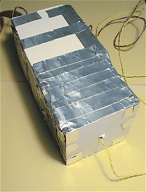
To illuminate the detector uniformly during testing you can construct a light box.
The one in these images consists of simple plates of polystyrene rapidly assembled with adhesive tape.
The electronic boards are on one end of the box. On the other end we find a small flashlight bulb.
In the middle of the box there are one or two sheets of white paper to serve as an effective light diffuser.
The bulb should be on an under voltage, to prevent saturating the CCD: often the lamp looks extinct to the eye when the CCD still sees it distinctly.
(remember that a CCD is very sensitive to infrared and is capable of easily seeing the heat emitted by the lamp, even if it doesn't emit any visible light).
The appearance of the images you make might depend on the quality grade of your CCD. Generally grade 2 CCD's show, when illuminated, discrete structures in the form of arcs because they originate from the edge of the wafer (a round slice of silicon) from which numerous detectors are produced. These forms are not annoying because they are removed during the image calibration process (flat-field operation). In addition, grade 2 and grade 1 CCD detectors have about 3 or 4 particularly hot pixels, pixels with a dark current way above average. These pixels disturb the reading of the CCD during the transfer of the charge packets in the image zone, thus producing vertical structures in the image.
 The upper image is typical for a KAF-0400 grade 2 CCD. It was obtained
by exposing the CCD for 4 seconds with enough light to cover half the dynamic
range of the camera. The temperature of the CCD was about +24°C. The hot pixels
are clearly visible. Three of them, particularly intense, disturb the reading
of 3 columns. The middle image is the result of subtracting a 4 second exposure
in total darkness from the upper image. This calibration operation permits
the removal of most of the hot pixels and gives the image a very smooth aspect.
But those 3 columns have not been treated right (they appear black because
the operation has overcorrected). A simple cosmetic treatment, consisting
of replacing the information in the defective columns with information from
the adjacent columns, permits a complete elimination of the problem imposed
by the bad columns (image below). Other techniques like median compositing,
give a similar result. It must be underlined that when the CCD is cooled,
the effect of the hot pixels will be less prominent, even almost non-existent.
Anyway, the columns that give trouble in this example represent 0.4% of the
surface of the CCD, which is quite insignificant. You can see worse examples
in the majority of CCD's used at professional observatories
! In short, a grade 2 CCD is perfectly
usable.
These images show two more examples of defects you can encounter in a CCD. On the left, the reading of the CCD is disturbed by a phenomenon called trap (trapping of the charges). On the right, it's a small dust speck in front of the silicon surface (dark cluster). All of these defects can, depending on their size and number, hinder the use of the detector. They can be easily removed with a simple image processing routine.
The upper image is typical for a KAF-0400 grade 2 CCD. It was obtained
by exposing the CCD for 4 seconds with enough light to cover half the dynamic
range of the camera. The temperature of the CCD was about +24°C. The hot pixels
are clearly visible. Three of them, particularly intense, disturb the reading
of 3 columns. The middle image is the result of subtracting a 4 second exposure
in total darkness from the upper image. This calibration operation permits
the removal of most of the hot pixels and gives the image a very smooth aspect.
But those 3 columns have not been treated right (they appear black because
the operation has overcorrected). A simple cosmetic treatment, consisting
of replacing the information in the defective columns with information from
the adjacent columns, permits a complete elimination of the problem imposed
by the bad columns (image below). Other techniques like median compositing,
give a similar result. It must be underlined that when the CCD is cooled,
the effect of the hot pixels will be less prominent, even almost non-existent.
Anyway, the columns that give trouble in this example represent 0.4% of the
surface of the CCD, which is quite insignificant. You can see worse examples
in the majority of CCD's used at professional observatories
! In short, a grade 2 CCD is perfectly
usable.
These images show two more examples of defects you can encounter in a CCD. On the left, the reading of the CCD is disturbed by a phenomenon called trap (trapping of the charges). On the right, it's a small dust speck in front of the silicon surface (dark cluster). All of these defects can, depending on their size and number, hinder the use of the detector. They can be easily removed with a simple image processing routine.
You have made a very important step in the construction of the Audine camera. Most important is the fact that you know now that the electronics are fully functional. Congratulations. Now, you only have to complete the mechanical assembly.