ELECTRIC DIAGRAM AND PISCO TELESCOPE INTERFACE PROGRAMMING
The PISCO electronic interface is connected to a PC serial port. This allows not to use the PC parallel port that is used by the Audine camera. It would have been possible to connect this interface on the camera extension port, but here too it has been decided to keep this port free for other applications. It must be noted that this interface is also available on laptop computers.
Choosing the serial port interface may look a little dangerous. However, PISCO makes a very simple use of the serial port so that it is not necessary to modify the default parameters of this port. Furthermore, it is not required to use complex electronics to manage the communication protocol. The serial interface is actually used as a parallel interface! The interface signal values are simply modified by using the values of some registry bits. With a parallel port, this can be achieved on a 8 bits bus, while only 3 bits can be used with the serial interface... However, this is more than we need!
At the cost of a small complexity overhead, the interface has been designed to offer at least 8 command bits, even if all these bits are not used today. Here is their definitions:
It must be noted that the Takahaashi mounts do not allow to modify the tracking speed through the computer. You must select first the tracking speed using the hand-controller switch (slow or fast). For most applications, you will chosse the fast move since PISCO is able to produce very short move commands.
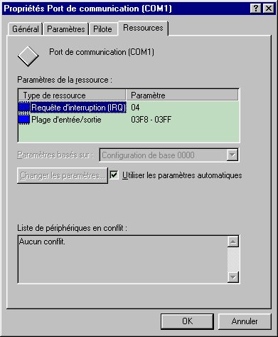
Most PCs have 2 serial ports called COM1 and COM2. In order for you to know the serial port addresses, you can open the Configuration Panel from the Windows Start menu. Click the icon System then click the tab Peripherial Manager. Click the list Port (Com & LPT). Finaly, click the item COM1 then the tab Resources.
Among the numerous registers of a serial port, only 2 of them are directly
used by our application. If COM represents the base address, then the useful
registries are at the addresses COM+3 (command registry) and COM+4 (modem command
registry). For information, the port COM+6 (modem state registry) gives access
to a set of bits that provide the values for some of the serial port pins (this
is useful to get the position of a filter wheel for instance). The following
table provides the relation between the available signals on the serial port
and the registries and bits addresses that need to be switched to activate and
read signals. Remember that the bit 0 (called the low weight bit) is
the first bit of an 8 bits word. The high weight bit of an 8 bits word
is the bit number 7.
|
|
|
|
|
|
|
|
|
|
|
|
|
|
|
|
|
|
|
|
|
|
|
|
|
|
|
|
|
|
|
|
|
|
|
|
|
|
|
|
For instance, to set the RTS signal to 1, you must turn on the bit 1 of the
COM+4 registry.
Two types of connectors are available for connecting a serial port: either
a DB9 or a DB25. In both cases, the connector must be of the male type on the
PC side. Here is the pin list for the two connector types:
|
|
|
|
|
|
|
|
|
|
|
|
|
|
|
|
|
|
|
|
|
|
|
|
|
|
|
|
|
|
|
|
|
|
|
|
|
|
|
|
The full electronic diagram is provided hereafter:

The interface is based on a 74HCT595 registry that transforms the serial information into a parallel information (up to 8 parallel bits). The serial port connector is called D1. We have chosen to use a DB9 pins description since it is the most used on laptop computers. Data bits are sent by the DTR pin on the 74HCT595 SI pin. The first bit to be loaded in the registry is the low weight one. The RTS signal is actually a clock that triggers the bit propagation within the registry. As an example, in order to set to 1 the bit 3 in the registry (that corresponds to the pin QD of the 74HCT595), one must first set to 1 the DTR signal then send 4 clock ticks on the RTS pin. Of course, between two clock ticks, it is possible to change the value of the DTR signal in order to write 0 and 1 within the registry.
While writing in the registry, the TxD signal must be in the low state. In order for the binary pattern to be visible on the output pins (QA... QH), the TxD signal must be set to 1. This is called a latch. This prevents the circuit to be on a non determined state while writing the registry. Without this security, we could observe random movements of the telescope...
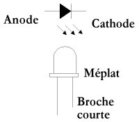
The RS-232 serial interface usually involves levels between +12V and -12V. The 1N4148 diodes block the negative voltage that could be dangerous for the 74HCT595 circuit. The 47K serial resistors allow to get the right command voltage for the 74HCT595. Several LEDs have been added (they are optional) in order to visualize the signal states. Do not forget to connect the serial port mass (pin 5).
At the registry output, the signals QA, QBn QC and QD are used to trigger the 4 analog switches from the 4016 circuit. These are the switches that will be connected in parallel to the hand controller push buttons. The signal to be switched are supposed to come from the telescope on a DB15 connected called D2 on the diagram. You are free to cable this connector as you want, but it is recommended to follow the inddications provided here. Please note that the signal QE is not used here. However, you can use it to control the telescope speed if your hand controller supports this function. In such a case, a second 4016 circuit must be added. The QA to QE signal states are visualized using the LEDs.
Take care that a 4016 circuit can only cope with small currents, around 1mA. It cannot be used to directly open or close a motor power supply for instance. In order to cope with higher currents (let's say 10 mA), you can use analogic switches such as MAX333 which are widely used within the Audine camera electronics. For even higher currents, a specialized integrated circuit will have to be used. The ULN2803 belongs to such a family with 8 output pins that can power devices up to 500 mA under 5V (or 200 mA under 12V).

If it is necessary to transport stong currents, the best solution is to use relays controled by a ULN2803 circuit. This system can be used in place of the 4016 circuit. In our application, the S0 signal would be for instance the QA signal of the 74HCT595, S1 would be QB, etc. Note that the power supply is related to the type of relay which is used. Note also that the ULN2803 circuite inverts the logical level applied to the inputs and that it has its own protection diodes (which is very well suited to driving relays).
For driving Takahashi mounts control, the 4016 circuit is perfect. This leads to a very low cost for the whole solution (less than $15.00). Only a few tens of minutes are required to assemble the full system on a Veroboard or DIP prototyping board.

Assembling the Audine telescope interface on a prototyping board. This is quite "messy", but this technics allows you to very quickly test the system. Note at the bottom the 74HCT595 and at the top the 4016. A few LEDs allow to check that the interface operates properly. Note the two connectors: a DB9 to the seriual interface and a DB15 to the telescope through a cable that makes the conversion for the Takahashi hand controllers.
The power supply is simply a 4.5V battery. Since the system consumption is very low, an alcaline bettery can easily last 10 nights before being replaced (especially if you do not use LEDs).
In order to program the interface, we have to generate 3 signals (DTR, RTS, TxD) by setting to 0 or 1 the correct bits in the registeries. It is wise to modify only the bit we are interested in and not to change the others. The following code, written in Visual Basic (but very easy to translate into an other programming language), implement the basic operations for our 3 signals.
' ------------------------------------------
' Serial
Port Writting
' Signal
DTR = pin 4 (connector DB9)
' Bit
0 of registry 4
' ------------------------------------------
' Set
to zero the DTR signal
r = outport(ComAdress+4, inport(ComAdress+4)
And &hFE)
' Set
to 1 the DTR signal
r = outport(ComAdress+4,
inport(ComAdress+4) Or 1)
' ------------------------------------------
' Serial
Port Writting
' Signal
RTS = pin 7 (connector DB9)
' Bit
1 of registry 4
' ------------------------------------------
' Set
to zero the RTS signal
r = outport(ComAdress+4, inport(ComAdress+4)
And &hFD)
' Set
to zero the RTS signal
r = outport(ComAdress+4, inport(ComAdress+4)
Or 2)
' ------------------------------------------
' Serial
Port Writting
' Signal
TxD = pin 3 (connector DB9)
' Bit
6 of registry 3
' ------------------------------------------
' Set
to zero the TxD signal
r = outport(ComAdress+3, inport(ComAdress+3)
And &191)
' Set
to zero the TxD signal
r = outport(ComAdress+3, inport(ComAdress+4)
Or 64)
The variable ComAdress holds the serial port base address (either &h2F8 or &h3F8).
The outport instruction format is: OUTPORT(ADDRESS, VALUE), where VALUE is the 8 bits word to be written at the physical address ADDRESS.
The inport instruction format is: VALUE = INPORT(ADDRESS), where VALUE is the 8 bits word red at the physical address ADDRESS.
A potential problem related to the Visual Basic programming is that it is not possible in this language to directly read from and write to physical addresses (this limitation does not exist in C). The instructions outport and inport used in the previous examples are not part natively of the language. These two instructions actually call some code located in a specific DLL developped in C. Here is the source code for these commands (to be compiled with Visual C++).
/*
OUTPORT : WRITE TO A PORT */
_declspec(dllexport) short
_stdcall outport(short adresse,short valeur)
{
outp(adresse,valeur);
return(0);
}
/*
INPORT : READ FROM A PORT */
_declspec(dllexport)
short _stdcall inport(short adresse)
{
return(inp(adresse));
}
And here is the Visual Basic declarations:
Public Declare Function
outport Lib "AUDINE.DLL" (ByVal adresse As Integer, ByVal valeur
As Integer) As Integer
Public Declare Function
inport Lib "AUDINE.DLL" (ByVal adresse As Integer) As Integer
Note that the functions outport and inport are implemented in the "AUDINE.DLL" DLL. If you do not have a C compiler to generate a DLL, you can simply use the AUDINE.DLL for your application. This DLL is available in the PISCO software directory.
To make simpler the program writing, 3 functions implement transparently the registry handling:
' ====================================
' Serial
port writing
' DTR
= pin 4 (bit 0 of register 4)
' ====================================
Sub WriteBit0(valeur As Integer)
Dim r As Integer
If valeur = 0 Then
r =
outport(ComAdress + 4, inport(ComAdress + 4) And &HFE)
r =
outport(ComAdress + 4, inport(ComAdress + 4) And &HFE)
r =
outport(ComAdress + 4, inport(ComAdress + 4) And &HFE)
Else
r =
outport(ComAdress + 4, inport(ComAdress + 4) Or 1)
r =
outport(ComAdress + 4, inport(ComAdress + 4) Or 1)
r =
outport(ComAdress + 4, inport(ComAdress + 4) Or 1)
End If
End Sub
' ====================================
' Serial
port writing
' RTS
= pin 7 (bit 1 of register 4)
' ====================================
Sub WriteBit1(valeur As Integer)
Dim r As Integer
If valeur = 0 Then
r =
outport(ComAdress + 4, inport(ComAdress + 4) And &HFD)
r =
outport(ComAdress + 4, inport(ComAdress + 4) And &HFD)
r =
outport(ComAdress + 4, inport(ComAdress + 4) And &HFD)
Else
r =
outport(ComAdress + 4, inport(ComAdress + 4) Or 2)
r =
outport(ComAdress + 4, inport(ComAdress + 4) Or 2)
r =
outport(ComAdress + 4, inport(ComAdress + 4) Or 2)
End If
End Sub
' ====================================
' Serial
port writing
' TxD
= pin 3 (bit 6 of register 3)
' ====================================
Sub WriteBit2(valeur As Integer)
Dim r As Integer
If valeur = 0 Then
r =
outport(ComAdress + 3, inport(ComAdress + 3) And 191)
r =
outport(ComAdress + 3, inport(ComAdress + 3) And 191)
r =
outport(ComAdress + 3, inport(ComAdress + 3) And 191)
Else
r =
outport(ComAdress + 3, inport(ComAdress + 3) Or 64)
r =
outport(ComAdress + 3, inport(ComAdress + 3) Or 64)
r =
outport(ComAdress + 3, inport(ComAdress + 3) Or 64)
End If
End Sub
In these 3 functions, it is easy to recognize the low level instructions that modify the bits state. You have certainly noticed that the same binary configuration is used three times. This is simply to guarantee that there is a few milli-seconds between two writes so that the interface electronics actually take into account the command issued by the software.
From these base functions, it is very easy to program the PISCO telescope interface. For example, to close the switch that control the negative declination movement, the bit 3 of the 74HCT595 register must be set to 1. In Visual Basic, this gives the following code:
' ================
' Delta
-
' (Bit
3)
' ================
Sub DecMoins()
Dim i As Integer
WriteBit2 0 '
Latch set to 0. This prevents that bit changes during configuration
'
are visible from outside
' All
the register bits are set to zero
For i = 1 To 8
WriteBit0 0
' 0 via DTR
WriteBit1 0
' 8 ticks on the Clock
WriteBit1
1
Next
WriteBit1 0
WriteBit0
1 ' DTR line set to 1
WriteBit1 1 '
Clock up
WriteBit1 0 '
Clock down. At this stage, the binary information resides in the low weight
bit of the registry.
WriteBit0 0 '
We push the bit in the registry
WriteBit1 1
WriteBit1 0 '
It is now in bit 1
WriteBit0 0 '
Let's do it again
WriteBit1 1
WriteBit1 0
WriteBit0 0 '
Let's do it again
WriteBit1 1
WriteBit1 0 '
Our information is now well positionned in the registry
WriteBit2 1 ' Latch set to 1. The registry programming is now visible from outside.
End Sub
The last difficulty resides in the initialization process. Before being able to play with the virtual hand controller and plug the telescope interface, it is mandatory to initialize the serial port and to set all the registry bits in a given state (all set to zero). This is the function of the initialization button that you will find in the tab Telescope of the PISCO software. When you click this button, you run the following code:
'
====================================
' Serial
Port Initialization
' Pulse
on bit 3 from register 4
'
====================================
Sub InitCom()
Dim r As Integer
Dim i As Integer
r = outport(ComAdress
+ 4, 0)
r = outport(ComAdress
+ 4, 0)
r = outport(ComAdress
+ 4, 0)
r = outport(ComAdress
+ 4, 8)
r = outport(ComAdress
+ 4, 8)
r = outport(ComAdress
+ 4, 8)
r = outport(ComAdress
+ 4, 0)
r = outport(ComAdress
+ 4, 0)
r = outport(ComAdress
+ 4, 0)
' Register
empty
WriteBit2 0 '
Latch set to 0
For i = 1 To 8
WriteBit0 0
' 0 written
WriteBit1 0
' 8 ticks on the Clock
WriteBit1
1
Next
WriteBit1 0
WriteBit2 1 '
Latch set to 1
End Sub
In order to get the full code for the function that implement the interface,
clic here. You will notice that the instructions to
modify the telescope speed or to adjust the focus are included but not used
in the current electronic interface. If you feel the need to do so, you can
very easily enhance the electronic diagram by adding a 4016 circuit that makes
use of the 74HCT595 unused pins. The code is fully operational within PISCO,
for instance through the focus buttons in the Telescope tab.
Back