
The heat drain that carries the cold from the Peltier module to the CCD chip has two holes located on he sides. These holes allow the insertion of thermal sensors. For instance one can insert a temperature sensor of the LM335 (TO-92 housing). This sensor is very simple to use, it supplies a potential difference that evolves linearly with temperature. The output potential difference is 1/10 of the temperature in degrees Kelvin (the temperature in degrees Kelvin is equal to the temperature en degrees Celsius plus 273).
The figure hereafter shows the wiring scheme of the LM335 element. A tension between +10 et +18V is applied on the pin 2 of the IC through the resistor R5 de 3.3KiloOhm. The pin 3 is connected to the ground. The pin 1 is unused. The tension proportional to the temperature is measured between the pin 2 and the ground. At about 25°C, the LM335 delivers a tension of about 3V. This tension change is of 10 mV by degree. For example, at 0°C one will measure about 2.75V. a numeric voltmeter with an accuracy of 0.01V is sufficient to measure the temperature with a precision of one degree, the conversion between volts and °C being easily performed mentally.
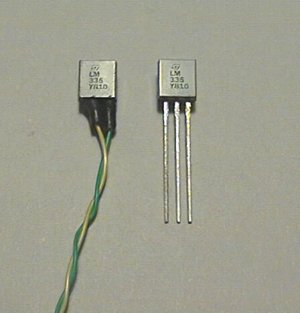
On the picture hereunder one can see how to prepare the LM335 IC for its use within Audine. One starts by cutting the pin 1 as short as possible since it will not serve in our application. The pins 2 and 3 are shortened to an approximate length of 3-4 mm. Then one solders some wrapping wire (very thin wire) to those pins. Here it matters to use electrical wire of a very small section in order to thermally isolate the warm parts of the camera as well as possible (multithread electrical wires should be avoided as much as possible in this very purpose). Solders are protected by some thermo-shrinkable sleeve in order to reduce the risk of any short.
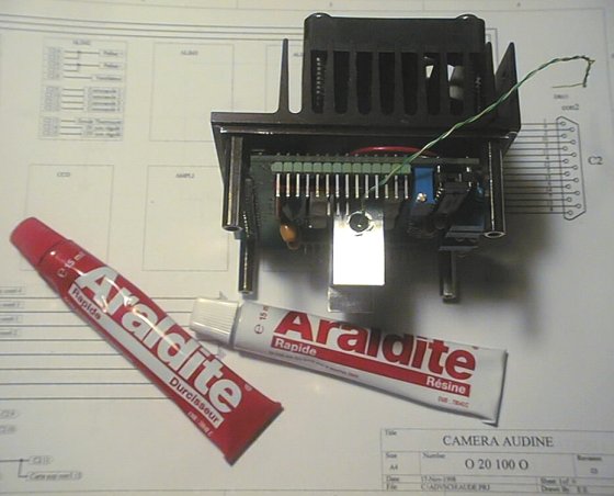
The sensor is sealed in one of the holes of the heat sink with some glue. We have used rapid 2-components epoxy glue (3 or 4 hour of curing time). After having thoroughly mixed the 2 components of the glue, fill a third of the hole with the help of a matchstick. One puts then the LM335 into the hole and completes filling the hole with more glue so the IC is completely cemented.
IMPORTANT: wait a sufficiently long time such that the glue has cured completely, before to mount the CCD. Indeed, when rushing things there is a non-negligible possibility that one of the mounting screws of the CCD gets glued as well to the thermal drain, which would make a later dismounting quite problematic.
For the electrical connection you can dispose 2 wires?? which go from the LM335, using for example the pins 14 and 15 of the connector DB15. It will then be necessary to connect the resistor and use an external power supply.
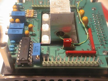
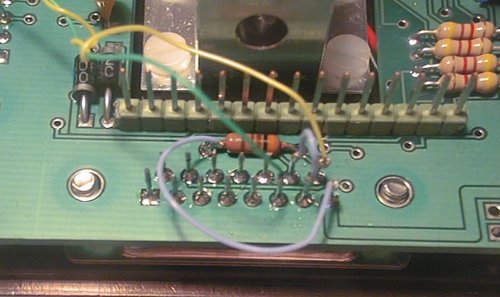
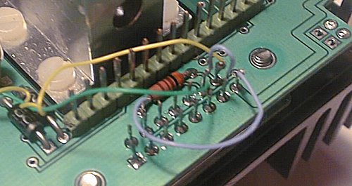
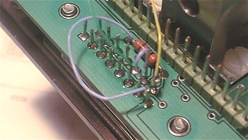
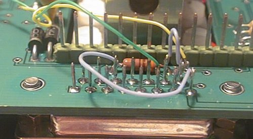
The pictures hereunder show another solution, which consists in using the R5
resistor placed on the lower electronic board, and the +12V which supply the
fan and its ground. In this graph, the voltage giving the temperature is directly
available from the pins 14 and 15 of DB15 without external component.
 |
 |
 |
 |
In function of the voltage (V) and the current feeding the Peltier module (I), the tables hereunder give the following variables:
Two situations are analyzed, one at an ambient temperature around 25°, the otherat an ambient temperature of about 0°C.
|
|
|
|
|
|
|
|
|
|
|
|
|
|
|
|
|
|
|
|
|
|
|
|
|
|
|
|
|
|
|
|
|
|
|
|
|
|
|
|
|
|
|
|
|
|
|
|
|
|
|
|
|
|
|
|
|
|
|
|
|
|
|
|
|
|
|
|
|
|
|
|
|
|
|
|
|
|
|
|
|
|
|
|
|
|
|
|
|
|
|
|
|
|
|
|
Other components than the LM335 can be used to measure he temperature. Some
are even of a simpler usage, such as the LM61 (this component can be power-supplied
directly with the +5V without resistor and it has a coefficient of 10 mV/deg
C). In the automobile stores one can find more and more easily off-the-shelf
sensors at a negligible price which display directly the temperature in degree
Celsius.
Back