THE AUDINE THERMAL SYSTEM
To be efficient, the CCD detector must be cooled down below 0°C. The Audine camera is equipped with a cooling system which is constituted with : a Termo Electric Cooler (TEC), a thermal cold tip, a radiator, a fan and thermal grease.

The Audine cooling system.

The TEC is the white element on the right. Beside is the thermal cold tip which links the cold face of the TEC to the CCD. A hole in the cold tip allows to implement a thermal sensor. The hot face of the TEC is linked to a radiator (via thermal grease) which dissipates the waste heat to the air thanks to the fan.
When it is electrically powered (take care to the polarity !), the TEC generates a temperature difference between its two faces thanks to the Peltier/Seebeck effect which generates, on the cold side, a cooling power. You can impose, depending of your power source control, either a certain voltage (below 7V) or a certain intensity (below 3.5A). If you impose a voltage, the intensity will be define by the TEC intrinsic characteristics (function of the temperature). If you impose the intensity, this will be the voltage which will be define by the TEC intrinsic characteristics. You cannot impose both the voltage and the intensity.
The temperature difference between the two TEC sides is function of the applied voltage (or intensity), of the mean temperature of the TEC and of the thermal flux which is collected by the cold face of the TEC. The thermal heat fluxes on the cold face of the TEC are :
1- Wr (<0), a cooling heat power which is due to the Peltier/Seebeck effect. It is function of the applied voltage or intensity.
2- Wj (>0), a waste heat power due to the Joule effect inside
the TEC. It is function of the applied voltage or intensity.
3- Wc (>0), a waste heat power due to thermal conduction between
the two faces of he TEC. It is function of the temperature difference between
the two sides.
4- We (>0), a waste heat power coming from the thermal cold tip
which collects different thermal fluxes inside the camera (convection, radiation,
CCD power)
Wr, Wj et Wc are given by the TEC intrinsic characteristics, We is function of the camera internal design. For thermal steady state, a thermal heat balance is given by Wr + Wj + Wc + We =0.
There is an optimum voltage (or intensity) for which the cooling effect is maximum. It is obtained when an increase of the applied voltage (or intensity) which leads to an increase of the cooling power (in absolute value) is compensated by the increase of the waste power coming on the cold face of the TEC (Joule, conduction from the hot face of the TEC and conduction from the cold tip).
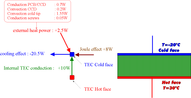
The order of magnitude of the thermal powers are given on the following figure, for Audine. One can notice that to obtain a temperature difference of 50°C between the two faces of the TEC, with 2W of thermal waste heat power on the cold face of the TEC, one must power the TEC with roughly 20W. Remark : 50°C of temperature difference between the two faces of the TEC, will not lead to 50°C between the external air and the CCD due to the other different thermal gradients in the system (see below).

Typical thermal heat balance for Audine.
The TEC used for Audine is CP 1.0-63-05L from MELCOR. Its size is 30x15x3.2mm. The maximum intensity is 3.9A for a maximum voltage of 7.6V.
The thermal cold tip is made of Aluminum (thermal conductivity of 120W/m/K) which is widely enough to guaranty negligible temperature gradient inside the cold tip (<0.5°C). It is useless to made cold tip with Copper.
The thermal fluxes collected by the cold tip (CCD dissipation, convection with internal air, radiative exchanges, conduction from the radiator via the bolts, conduction from the PCB via the CCD) is a major parameter of the thermal efficiency of the camera. It is important to minimize theses parasitic fluxes. Consequently :
The fin radiator is made with Aluminum. It is associated with a fan to maintain its temperature the more closest to the external air temperature despite the power dissipated on the hot side of the TEC (which is thermally linked to the radiator by thermal grease). The radiator is black anodized in order to increase the radiative effect toward the external environment.
For the maximum cooling capacity, 20W must be dissipated. A fan is absolutely necessary. Indeed, without fan the radiator temperature will be hotter by about 40°C than the external air (natural convection without wind), which is not acceptable. Thanks to a fan, this temperature difference is limited to 8°C.
Take care : If the fan is not working it is imperative to supply the PEC with voltage lower than 3.5V (or 1A). With higher voltage (or intensity) there is a significant risk of TEC divergence which can leads to the TEC performance reduction or breakdown.
To increase the radiator global efficiency, it is possible to use a more powerful fan, to increase the fan area or to use a water cooled radiator (the use of cooper is useless).
But, with a perfect radiator (radiator temperature = external air temperature), one estimates that the CCD temperature reduction will be about only -3°C (a reduction of 1°C one the radiator will not result of a reduction of 1°C on he CCD temperature). One have estimated that for Audine the CCD temperature reduction was not significant with regards to the simplicity and compacity of the camera.
The thermal grease is an essential component for the thermal performance of the camera. This grease guaranty a good thermal contact, and consequently a minimum temperature difference, between the CCD and the cold tip, between the cold tip and the TEC cold side, and between the TEC hot side and the radiator (this is the more important). Indeed, for each contact, the temperature difference between the hot side of the interface (where comes from the thermal flux) and the cold side of the interface (where goes the thermal flux) is proportional to the thermal flux crossing the contact (in W) multiplied by the thermal conductance (=1/resistance) of the contact (in W/m²/K). This thermal conductance is very dependant of the materials and of the contact pressure. For exemple, a typical thermal conductance between two surfaces is typically about 500W/m²/K without grease and moderate contact pressure. For our TEC (1.5cm x 3.0cm), we would have, without grease, a temperature difference of about 4.4 °C for 1W crossing each interface. On the cold face, the crossing thermal flux is about 2.5W, which would lead to a temperature of the cold tip (this is the hot side of the interface) higher by about 10°C with regard to the temperature of the cold face of the TEC. Thus is a pity, but it is not catastrophic. However, for the hot face of the TEC, the crossing thermal flux is about 20W (at the optimum), which would lead to a temperature of the hot face of the TEC (this is the hot side of the interface) higher by about 90°C with regard to the radiator temperature. This is clearly not acceptable and quite dangerous for the TEC.
By using thermal grease, one can expect to have a thermal conductance of about 5000W/m²/K. The temperature difference at the TEC cold face interface is about 1°C, and the temperature difference at the TEC hot face is about 10°C. At the CCD/cold tip interface the thermal difference is below 0.5°C.
One can see that, even with thermal grease, there is a potential improvement at the TEC hot face interface, which would lead to a reduction of about 4°C on the CCD, assuming a quasi perfect thermal contact. One solution could the to glue the TEC on the radiator with conductive glue while applying, with a tool, a significant pressure. This is however not recommended due to the significant risk of failure due to thermoelastic effect (Ceramic has a coefficient of thermal expansion very low in comparison with the one of glue and aluminum. Consequently, when the temperature decrease the ceramic does not retracts while the radiator and the glue wants to, which could leads to a rupture).
A thermal mathematical model have been developed in order to predict the temperatures
on different locations of the camera.
On the following figures, different temperatures are plotted function
of the intensity crossing the TEC, for a non thermally insulated cold tip and
external air at +25°C. One can notice, first of all, that there is a good
correlation between the thermal predictions and the cold tip and radiator measurements
(specific thermocouples), and secondly, that the optimum of the cooling is obtained
for typically 3A (which correspond to roughly 6.5V).

Thermal predictions and temperature measurements on the CCD and the radiator for a non insulated cold tip and an external air at +25°C
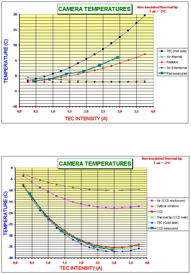
The following curves presents the thermal predictions for external air at -2°C.

Thermal predictions and temperature measurements on the CCD and the radiator for a non insulated cold tip and an external air at -2°C
For the Audine camera without thermal insulation of the cold tip (but correctly assembled) and the optimum supplied intensity (about 3.5A), you should obtain a temperature around -15°C on the CCD with external air at +25°C and -36°C with
However, it is possible to obtain better thermal performances with the following modifications :
Remark 1 : If you adopt two (or more) of these modifications, you will not obtain the sum of the temperature reduction.
Remark 2 : By using a very cheap (20$) standard PC power supply source (+5V), the intensity will be about 2.4A which is not the optimum, but it is reasonably acceptable. The cabling of these item is very simple.

On the right, a PC power source which is ideal for the TEC power supply.

CCD temperature evolution function of time when applying +5V to the TEC. Freezing temperatures are obtained after about 2mn.
Last, but not least, a thermal sensor can be put inside the cold tip (temperature very close to the CCD temperature). This temperature information can be used to accurately control the CCD temperature, while it is not indispensable to efficiently operate your camera. The Audine baseline is to cool at the maximum possible the CCD (no temperature margin necessary for the thermal control). The thermal noise can be a posteriori estimated and subtracted to the image by numerical treatment.