ASTRONOMICAL FILTERS SPECTRAL
TRANSMISSION
Summary
Astronomik
CCD Halpha (two filters)
Custom Scientific Halpha
Astronomik
CCD [SII]
Astronomik
Visual Hbeta (two filters)
Astronomik
Visual [OIII]
TeleVue [OIII]
Meade
[OIII]
Lumicon [OIII]
Astronomik
IR block
Baader IR/UV
Baader
Fringe-Killer
Edmund Optics IR
Canon
350D internal IR rejection filter
Nikon
D70 internal IR rejection filter
Astronomik
UHC
Lumicon Deep Sky
Lumicon
UHC
Baader UHC-S
IDAS
LPS-P1
Meade
nebular
TeleVue NebuStar
Lumicon
Halpha Pass
Baader Neodymium
Pollution light rejection power
Special thanks to COSMODIff,
3 rue Romiguières, 31000 Toulouse (France), which provided us some filters of
this performances evaluation.
Remerciement
spécial à COSMODIff,
3 rue Romiguières, 31000 Toulouse (France), qui a fourni quelques-uns des filtres
de cette évaluation de performances.
Protocol. The filters transmission of this page
are acquired with a LISA spectrograph and a modified Canon 350D as detector
(the internal IR cut filter of this DSLR is removed). The spectral density of the light source
(halogen lamp), the efficiency of the spectrograph and of the detector
are taken into account for construct the true relative transmission curve.
A neon lamp and a mercury
lamp are used for spectral calibration. The spectra are processed with VisualSpec.
The effective aperture number of the optical beam used
for the measure is near f/8 (limited by the acceptance angle of the spectrograph) and
except some situations, the beam axis is normal to the filter surfaces.
This beam is assimilable to a collimated beam (slow converging).
If the filter is tilted by an angle a in a collimated beam, the primary effect is a shift of peak transmittance toward shorter wavelengths. If l is the peak wavelength at angle of incidence a, if l0 is the peak wavelength at 0° angle of incidence (the present measures) and if n is the effective refractive index of the coating, the relation between these quantities is
![]()
The values n=1.4 and n=2.0 are representative of inside indice of interference filters (the exact value is determined by the coating materials used and the sequence of thin-film layers in the coating).
When interference filters are used in a converging beam (as is the case in a telescope), the new transmission curve result from the integration of the rays at all of the angles within the cone. For moderate speed systems (f/2.5 or slower), the shift in the peak wavelength can be approximately predicted from the above tilted collimated beam formula: the peak wavelength shifts is about one-half the value that it would shift in collimated light at the cone's most off-axis angle. If lm is the new "central peak wavelength" when the filter is used in the converging beam, we have the following approximate relation
![]()
where b is the max incidence angle of light in filter, i.e. the cone angle
![]()
N0= aperture number of the telescope
Suppose an f/5 telescope and the Ha line (at l0=6563 A). Whe have N0=5, b=0.1 rd and lm=6559 A if n=2.0 and lm=6555 A if n=1.4.
The secondary effects a the converging beam are
a broadening of
the transmission curve and a depression of the peak transmittance.
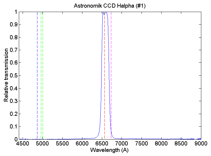
Relative
transmission curve of an Astronomik CCD Ha filter (filter
number 1). From left to right the dashed
lines indicates the position of Hb (bleue), [OIII] doublet (green), Ha at 6563 A
(red)
and [SII] line at 6730 A (cyan).

Detail
of an Astronomik CCD Ha filter
transmission near Halpha line (red dashed line). Filter #1
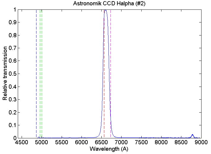
Relative
transmission curve of an Astronomik CCD Ha filter (filter
number 2). From left to right the dashed
lines indicates the position of Hb (bleue), [OIII] doublet (green), Ha at 6563 A
(red)
and [SII] doublet at 6730 A (cyan).

The central wavelength of the filter #2
is significantly shifted
toward the bleue. Efficiency at the Halpha level is reduced by a factor 0.9
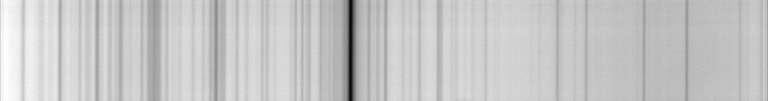
comparatively to an hypothetical correct filter. The proof...


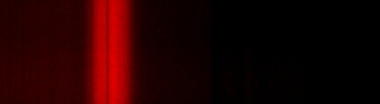
Up
image, part of the sun spectrum taken with the LISA spectrograph (intermediate
resolution mode - 600 grooves/mm grating). Middle image, same observation condition,
only the Astronomik Ha filter #2
is added in the optical beam. The red shift of
the transmission curve relative to the Halpha line position is very evident.
Down image, an Edmund Optics Halpha is now used (ref. 43-086). The central wavelength
position is now correctly adjusted (but in the same time the peak transmission
of the Edmund filter is near 50% only, and near 90% for the Astronomik filter).
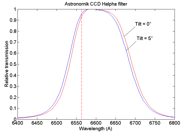
The
Astronomik CCD Halpha filter #2 for two incident angles. The curves show progression in pass-band
when the angles of incidence of the f/8 beam are varied from 0° to 5° (simulate approximately the
marginal rays of a f/5.6 telescope). The dashed line indicate the position of
Ha.
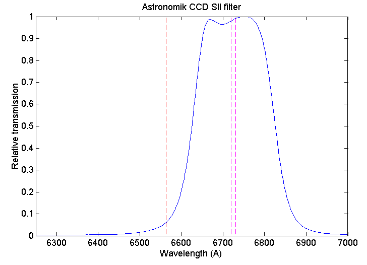
Relative
transmission curve of an Astronomik CCD SII
filter. The red dashed line indicate
the position of Ha line (at 6563 A). The magenta lines indicate the position
of [SII] doublet (at 6719 and 6730 A).

Relative
transmission curve of a Custom Scientific Halpha
656.3/4.5nm filter. The peak transmittance of this narrow band filter is significantly
shifted toward the red (F/8 aperture optical beam).


Independent
check of the spectral transmission by using the high resolution spectrograph
LHIRES3. Up image: standard LHIRES spectrum
of the sun - the Halpha line is at the center (sampling of 0.34 A/pixel). Middle
image: the Custom Scientific Halpha filter is inserted in the optical beam (just
front the entrance slit).The peak transmittance is not superposed to Halpha.
Down image: the filter is tilted by a severe angle of 16°. The peak transmittance
is now on Halpha line.
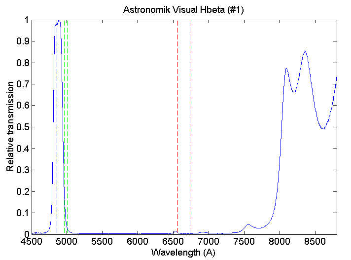
The
Astronomik Visual Hbeta filter #1 spectral
transmission. Of course, an IR
blocking filter is necessary for use this filter in conjunction with an infrared
sensitive camera (CCD, moded DSLR, ...).

Detail
of the Astronomik Hbeta filter #1 near Hbeta spectral line. The
bleue dashed line indicate the position of Hb line (at 4861 A). The Cyan dashed
lines indicate the position of the [OIII] doublet at 5007 A (the most intense
component)
and 4959 A.
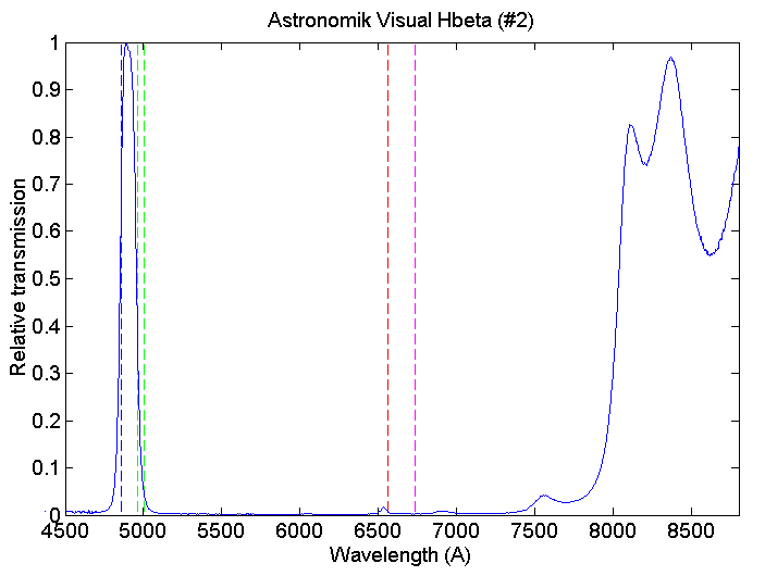
The
Astronomik Visual Hbeta filter #2 spectral transmission. From left to right the dashed
lines indicates the position of Hb (bleue), [OIII] doublet (green), Ha at 6563 A
(red)
and [SII] line at 6730 A (cyan).
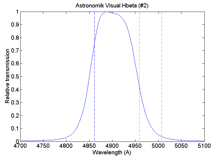
Detail
of the Astronomik Photographic (or Visual) Hbeta filter transmission curve. The
bleue dashed line indicate the position of Hb line (at 4861 A). The Cyan dashed
lines indicate the position of the [OIII] doublet at 5007 A (the most intense)
and 4959 A.
The same problem is encounter about the peak transmission of the bandwidth as the Astronomik Ha filter #2. The shift is more severe here ! Another proof...
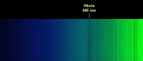

Up
image, part of the sun spectrum taken with the LISA spectrograph. Down image,
same observation condition, only the Astronomik Hb filter #2
is added in the optical
beam. The Hb line is nearly out of band of the filter.

The
Astronomik Photographic (or visual) Hbeta filter #2 transmission for three incident
angles. 0° tilt curve, the f/8 input beam is normal to the filter surfaces.
5° tilt curve, the filter is tilted by a angle of 5° relative to the f/8 input
beam (simulate approximately the marginal rays of a f/5.6 telescope). 6.5°
tilt curve, the filter is tilted by a angle of 6.5° relative to the f/8 input
beam (simulate approximately the marginal rays of a f/4.3 telescope). The
dashed line indicate the position of Hb.
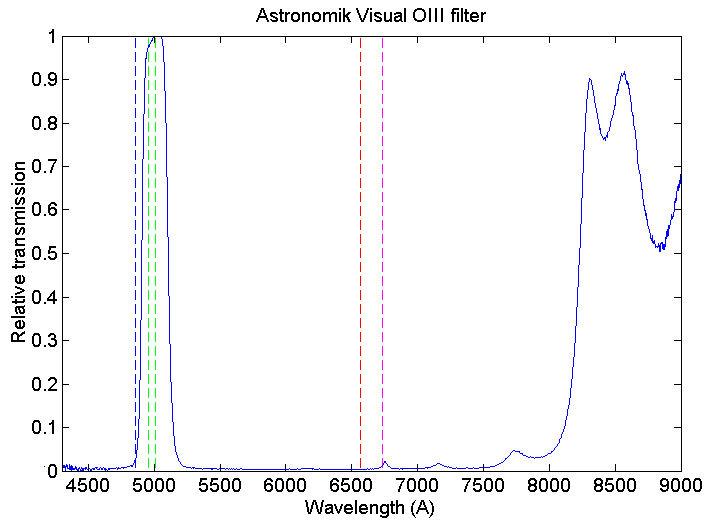
Transmission
curve of an Astronomik Visual OIII filter.
From left to right the dashed
lines indicates the position of Hb (bleue), [OIII] doublet (green), Ha at 6563 A
(red)
and [SII] line at 6730 A (cyan).
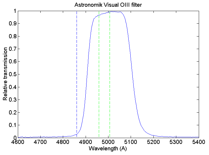
Detail
of the Astronomik Visual [OIII] filter transmission curve.

Transmission
curve of an Astronomik CCD [OIII] filter.

Detail
of the
Astronomik CCD [OIII] filter transmission. The bleue dashed line indicate
the position of Hb line (at 4861 A). The Cyan dashed lines indicate the position
of the [OIII] doublet at 5007 A (the most intense) and 4959 A. This filter
is not a pure oxygen filter, some light of neutral hydrogen is also transmitted.
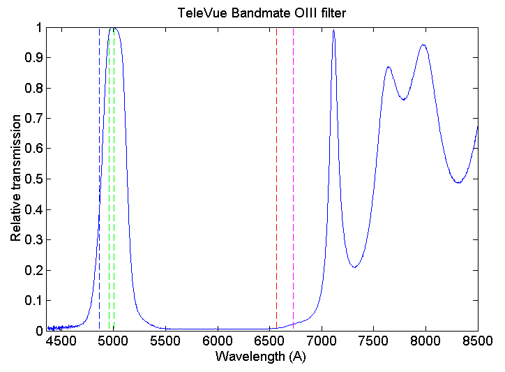
Spectral
transmission of the TeleVue Bandmate [OIII]
filter.

Spectral
transmission of the Meade [OIII] filter.
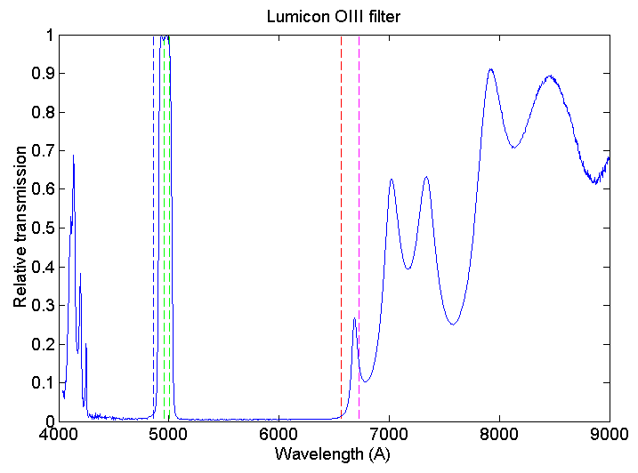
Spectral
transmission of the Lumicon [OIII]
filter.
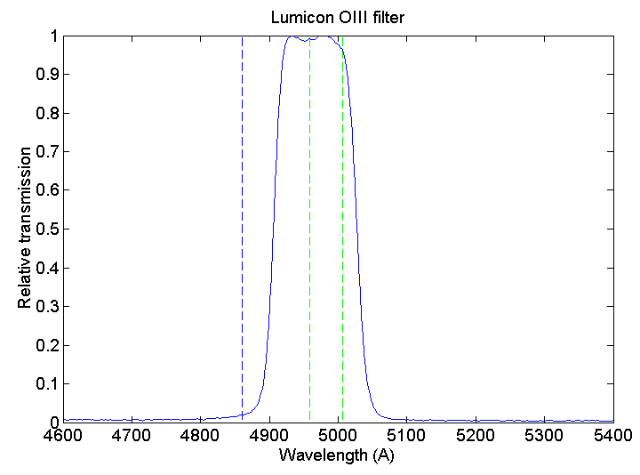
Detail
of the Lumicon [OIII] filter.
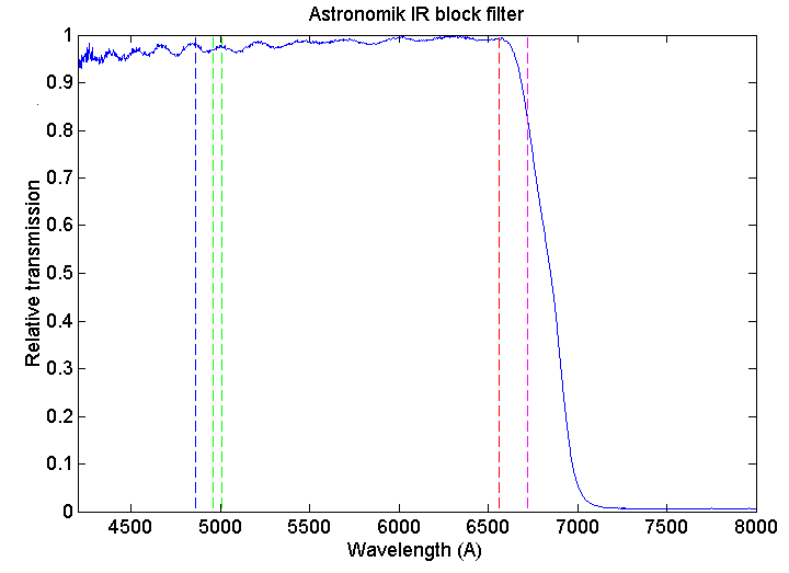
The
Astronomik IR block filter spectral transmission. From left to right the dashed
lines indicates the position of Hb (bleue), [OIII] doublet (green), Ha (red)
and [SII] doublet (cyan).
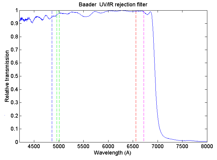
The
Badder UV/IR rejection filter spectral transmission. From left to
right, the dashed lines indicates the position of Hb (bleue), [OIII] doublet
(green), Ha (red) and [SII] doublet (cyan).
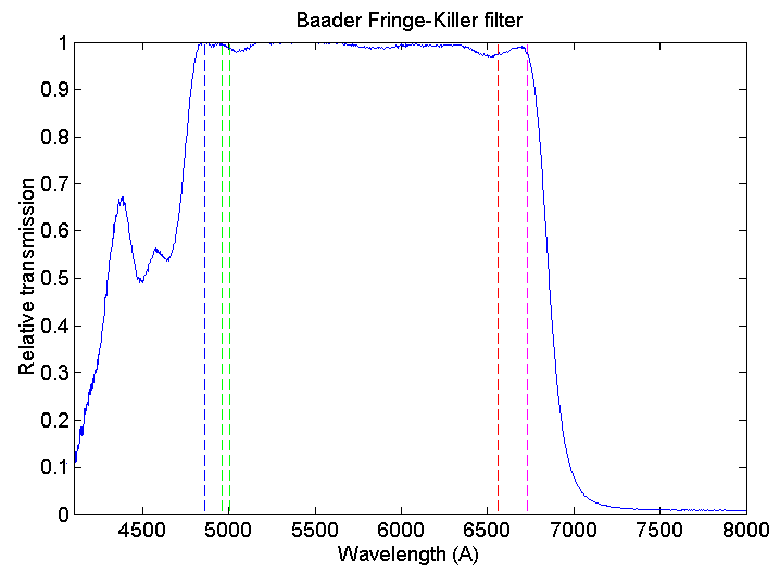
The
spectral transmission of a Baader Fringe-Killer
filter.
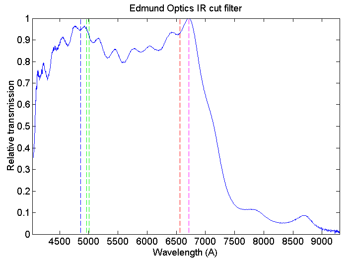
The
Edmund Optics IR rejection filter spectral transmission.
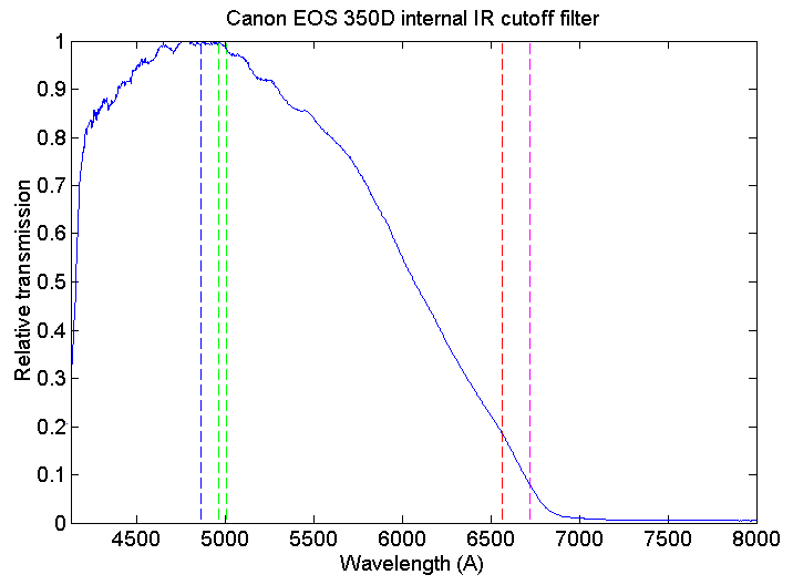
The
Canon EOS 350D internal IR cut filter. From left to
right, the dashed lines indicates the position of Hb (bleue), [OIII] doublet
(green), Ha (red) and [SII] doublet (cyan).
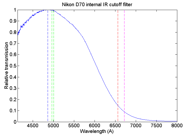
The
Nikon D70 internal IR cut filter. From left to
right, the dashed lines indicates the position of Hb (bleue), [OIII] doublet
(green), Ha (red) and [SII] doublet (cyan).
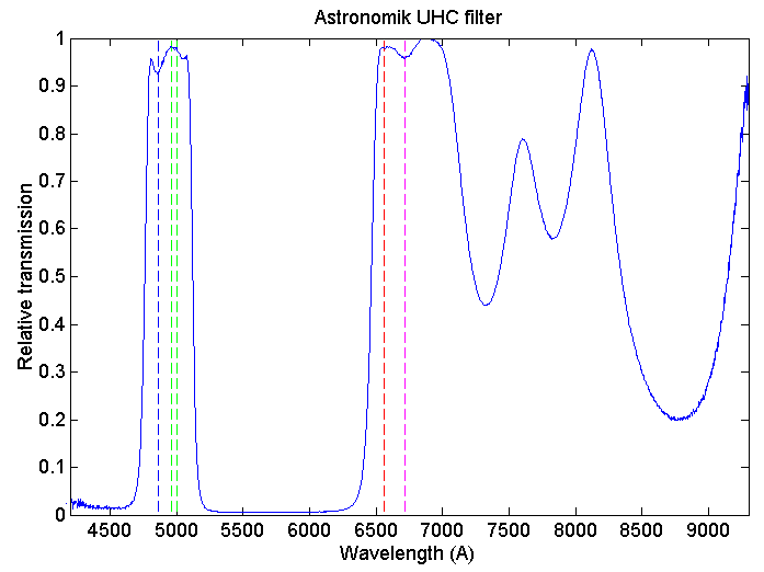
The
Astronomik UHC filter spectral transmission. From left to right, the dashed
lines indicates the position of Hb (bleue), [OIII] doublet (green), Ha (red)
and [SII] doublet (cyan). Click here for an example
of use.
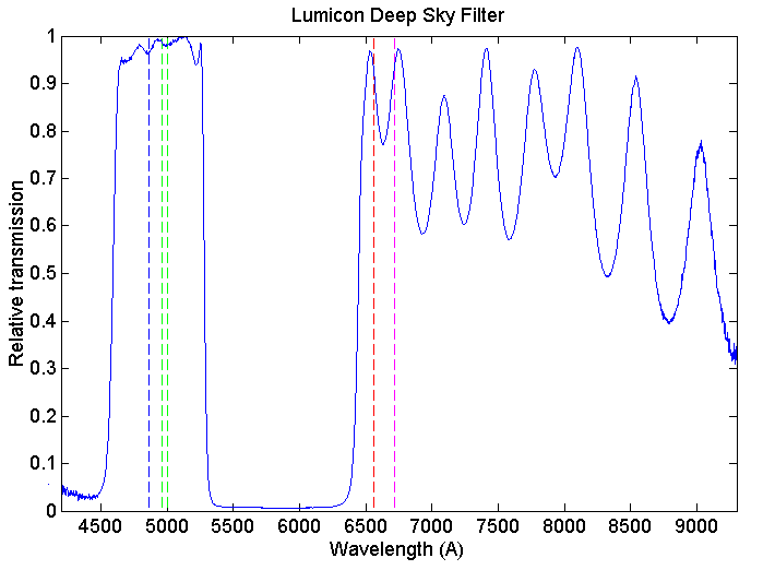
The
Lumicon Deep Sky filter spectral transmission.
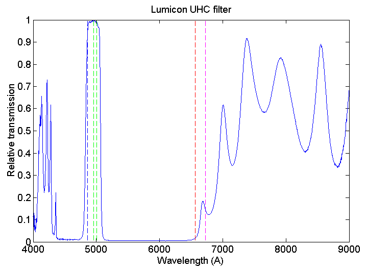
Spectral
transmission of the Lumicon UHC filter.

Detail
of the spectral transmission of the Lumicon UHC.
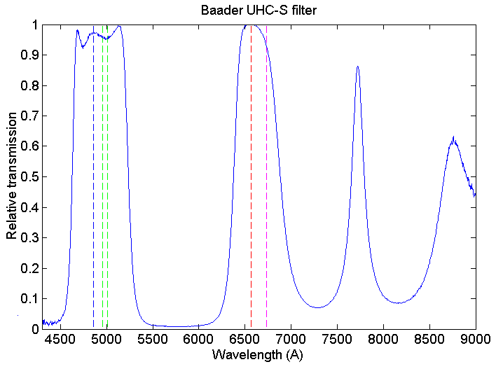
The
Baader UHC-S spectral transmission.
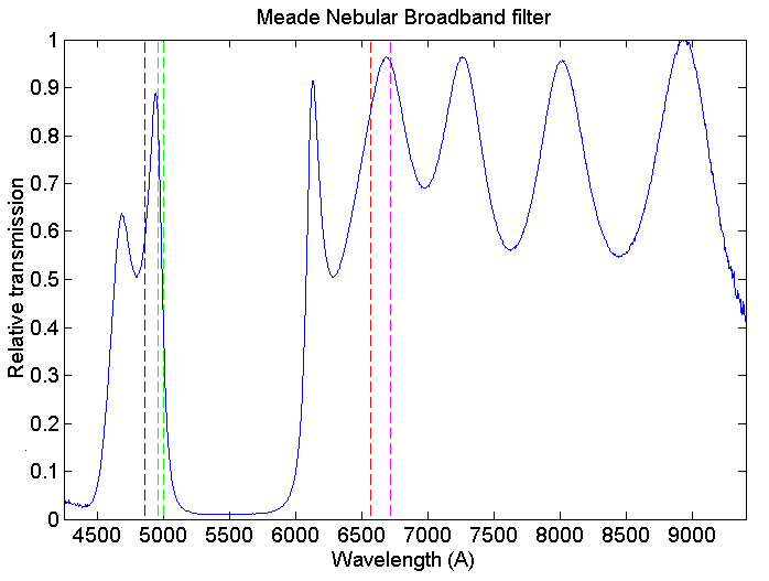
The
Meade Nebular Broadband filter spectral transmission.
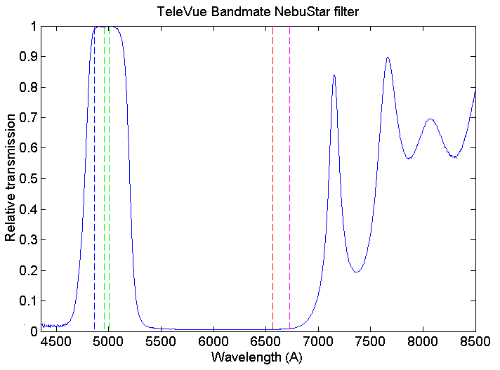
The
transmission curve of a TeleVue NebuStar filter.
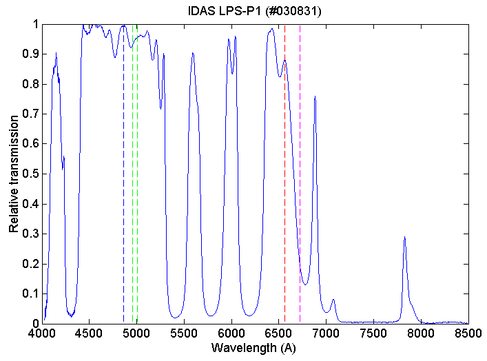
The
transmission curve of a IDAS LPS-P1 filter. The transmission curve of the tested
filter is globally shifted toward the blue by about 50 angstroms relative
to the given constructor spectral curve. The Halpha position is indicated by
the vertical dashed red
line.

Several
verification have been done to avoid possible errors. Here for checking
the measure, the quasi simultaneous observation of the IDAS transmission (the source is a halogen lamp) and of
the neon gases emission.

Examples
of pollution rejection filter and IR cutoff filter combined. In the sense of
nebula imagery only, the Astronomik solution is better because the bleue band
pass is narrower (better rejection of pollution). Click here for some examples
of use.
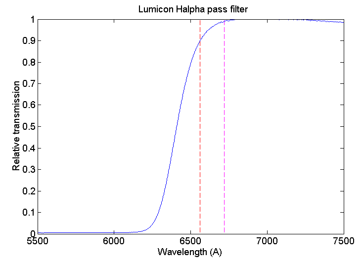
The
Lumicon Halpha Pass filter. From left to right the dashed lines indicates
the position of Ha (red) and [SII] doublet (cyan).
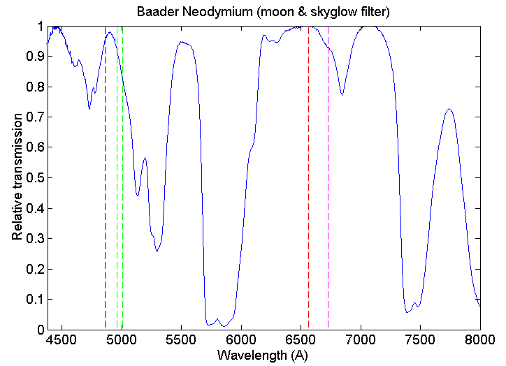
The
spectral transmission of the Baader Neodymium
(Moon and Skyglow filter).
LIGHT POLLUTION REJECTION POWER

Spectral
distribution of my artificial street light, dominated by the sodium (click
here for explanations about the content of this spectrum). LISA spectrograph
and Canon 350D are used.

The
light of an OSRAM hand poked lamp (fluorescent tube) is added. The spectrum
show for example useful Hg lines for a precise spectral calibration. It is one
of the emission line lamp used for this studies.
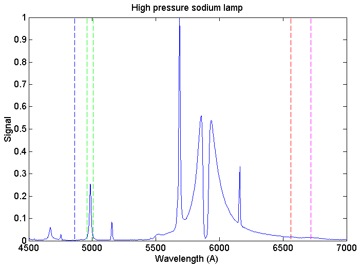
Response
of the modified Canon 350 and of the spectrograph to light of a HPS lamp.
|
|
|
|
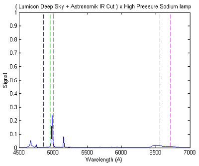
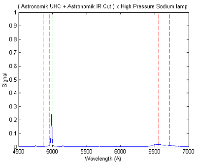
The HPS lamp observed through some LPR filters. The selected filters permit to observe simultaneously Halpha, Hbeta, OIII lines and SII with a DSLR sensor. From left to right, IDAS LPS-P1, Lumicon Deep Sky, Astronomik UHC. The rejection power of the IDAS filter is relatively poor. The Astronomik UHC is the better filter tested here in the sense of nebulae observation under severe light pollution with a DSLR camera (and for capture in one shot the major nebulae emission lines). Only the Na doublet (4978 and 4983 angstroms) is present. The Lumicon Deep Sky is only slightly inferior.