Image
JUP_R.PIC

Image
JUP_G.PIC

Image_JUP_B.PIC
Aide IRIS
Techniques d'imagerie couleurs
Comment
produire une image couleur à partir de trois images noir et blanc ?
En premier, vérifier que l'on a bien choisi le format d'image PIC (boite de dialogue Réglages du menu Fichier).
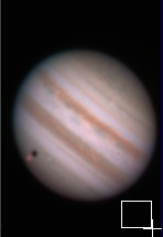
Considerer les trois images noir et blanc de Jupiter suivantes, acquises respectivement au travers de filtres rouge, vert et bleu :
|
|
|
|
Ouvrir la boite de dialogue (L)RGB du menu Visualisation. Entrer les noms des trois images dans les champs correspondant :

Cliquer sur Appliquer. Une image couleur d'affiche, mais clairement, les 3 couches ne sont pas parfaitement alignées (un liseré coloré est visible au limbe)...

Selectionner l'option Rouge et définissez un pas de déplacement de un pixel. Agir surt les flèches pour aliger la couche rouche sur l'image verte :

Pour chaque click sur une fèche, la couche rouge glisse d'un pixel par rapport aux couches verte et bleu. Vous pouvez entrer une valeur fractionnaire de pas. Vous pouvez aussi changer à tout moment des seuls de viusalisation.
A présent, selectionnez la couche bleu, et alignez là interactivement par rapport aux couches rouge et verte.
Lorsque l'alignement des 3 couches parait correct, cliquer OK et sauvegarder l'image 48 bits ainsi produite dans le fichier de votre choix. Par exemple :
>SAVE JUPITER
Si nécessaire, pour rendre le fond de ciel noir, sélectionner une hors du disque de la planète à la souris et taper la commande BLACK depuis la console :

>BLACK
Vous pouvez ajuster la balance du blanc à partir d'une partie de la planète supposée par nature blanche, puis lancer la commande WHITE :

>WHITE
Le résultat t

Pour réaliser la balance du blanc sur la planète Saturne utiliser les anneaux. Pour la planète Mars se servir de la calote polaire si elle est visible. Si vous disposez de la valeur numérique des coefficients RGB suite à une précédente calibration vous pouvez utilser la boite de dialogue Balance RGB du menu Photo numérique :

Pour accroite le contraste de certains détails, utiliser la boite de dialogue Ondelletes du menu Traitement. Par exemple ici

Cliquer sur OK pour valider le rehaussement de contraste. Pour exeporter l'image vers un format d'image infographique vous pouvez par exemple faire :
>SAVEJPG JUPITER 1
Le fichier JUPITER.JPG est créé dans le répertoire de travail. La valeur 1 du second paramètre indique qu'il n'y a pas de compression pratiquée (tous les détails sont préservés). Vous pouvez aussi exporter l'images avec un codage sur 48 bits en employant les formats PNG ou TIFF. Pour cela ouvrir la boite de dialogue Sauver du menu Fichier et selectionner le type de fichier. Vous pouvez de plus depuis la console faire :
>SAVEPNG JUPITER
Bien sur la boite de dialogue (L)RGB est utilisable pour registrer les plans couleurs d'une image du ciel profond, pour compenser la réfraction atmosphérique différentielle ou autre :
|
|
|
Comment séparer les couches RGB d'une images 48 bits ?

Images
des Pléiades (EOS350D + objectif de 50 mm).
Ouvrir la boite de dialogue Séparation RGB du menu Photo numérique et entrer par exemple :

La commande produit les 3 fichiers images R.PIC, G.PIC and B.PIC correspondant respectivement aux couches rouge, verte et bleue de l'image 48 bits de départ :
|
|
|
|
La même fonction peut être réalisée depuis la console avec la commande SPLIT_RGB . Par exemple :
>SPLIT_RGB R G B
Pour réaliser la séparation trichrome d'un jeu d'images 48 bits, utilser la commande SPLIT_RGB2 command. La syntaxe est
SPLIT_RGB2 [ENTREE] [R] [G] [B] [NOMBRE]
Par exemple, pour séparer les composantes de la séquence M45_1, M45_2, M45_3, faire :
>SPLIT_RGB M45_ R G B 3
Les images suivantes sont générées : R1, R2, R3, G1, G2, G3, B1, B2, B3.
Pour recombiner les composantes RGB vous pouvez utliser la boite de dialogue (L)RGB, nous l'avons vu, mais aussi la commande TRICHRO depuis la console :
>TRICHRO R G B
ou une forme plus compacte :
>TR R G B
Transformation HSI
The RGB2HSI command convert the traditional RGB representation of a true colors image to the HSI space (Hue, Saturation, Intensity space). This convertion produce three images. The hue image correspond to the dominant colors (color tone), the saturation image correspond to the purity of colors and the intensity correspond to the magnitude of the signal in the colored image.
More precisely:
I) In the hue image, pixels that are predominantly red in the trichromatic image will be represented by high levels, pixels that are predominantly green will be represented by intermediate levels, and pixels that are predominantly blue will be represented by low intensity levels. If the levels are represented by the angles from 0° to 360°, red corresponds to 0°, green to 120°, blue to 240°, red again to 360°.
II) In the saturation image the areas of the tri-colors image where the colors are purest will be represented by the high levels. Low saturation results in a gray aspect images, middle saturation produces pastels and high saturation results in vivid colors.
III) The intensity image is the one that most resembles each of the monochromatic components of the tri-colors image. This image expresses the average intensity of the three fundamental colors component in a grey form.
|
|
Colorimetric transformation is a powerful tool that can profoundly modify the appearance of color images. In particular, the HSI representation is often used in science to enhance specific colored details in an image. If they are properly used, transformations between the HSI and the RGB systems allow you to reveal subtle colored characteristics in images and thus make them easier to interpret.
For example, consider this image of the horse nebula:

EOS350D
+ 50 mm lens.
Extract the R, G and B components:
>SPLIT_RGB R G B
|
|
|
|
Now compute the H, S and I transform. The syntax of RGB2HSI command is:
RGB2HSI [R layer] [G layer] [Bleu layer] [H layer] [S layer] [I layer]
Here
>RGB2HSI R G B H S I
|
|
|
|
The inverse of RGB2HSI command is HSI2RGB command
Example, increase the saturation of the horse nébula. For this multiply, the saturation image by a coefficient and return to the RGB space:
>LOAD S
>MULT 1.5
>SAVE
S
>HSI2RGB H S I RR GG BB
>TR RR GG BB

The
method used for increase saturation on image processing software.
Here another example of HSI transform concerning the Messier 27 nebula:

True
colors image of
M27 (Takasahi Epsilon 160 telescope + Audine KAF-0400 camera).
|
|
|
|
|
|
Below, some Moon images carried through interference filters. Instrumentation: Takahashi 5-inch refractor at f/10 + KAF-1600 directly at the focus.
|
|
Tip: You can also invoque the Saturation adsjustement command of View menu, the algorithm is very similar.
The following strategy should be used for compute
an albedo image for science. Suppose a couple of color images (R&G
or R&B, etc):
1. Calculate the spectral ratio of the two images (one is
divided by the other). The result is the image H.
2. The I component is one
of the monochromatic images (or mean of the two images),
3. The S component
is set to a constant level (1, for example),
4. Transform from HSI to RGB,
then visualize the resulting tricolor images.
The result of this later processing
is an image whose level represents the albedo of
the object, and whose color represents the spectral signature (here a spectral
ratio).
More generaly, the hue and saturation components defines the chromaticity of a color. It is important to note that chromaticity and intensity of a color can be considered independently. The very interest of HSI space is that it decorelate color tone and hue from brightness. This is why we can replace in HSI space the I component by a new high quality "Luminance" image. While returning then in the RGB domain, we preserve the original colors, but with a boost in the details, a much cleaner image and a much high SNR comparatively has the initial true colors image. It is the basic principle of the popular LRGB techniques.Click here for an Iris tutorial about LRGB.
Analyse en composante principale
The Principal Component Analysis (PCA) corresponds to a coordinate transformation of a color image that is represented in the space of fundamental colors (Red, Green, Blue). After the transformation, the axes are the eigenvectors of the covariance matrix of the three input images. The three resulting images are obtained by projecting the three starting axes (R,G,B) onto the three resulting axes. Without going into the mathematical details, it is interesting to choose this coordinate system because it defines three new images that are as uncorrelated from each other as possible, from the chromatic point of view.
The first axis, also called the principal axis, corresponds to the largest eigenvalue of the covariance matrix. Generally, this axis is very close to (but not coincident with) the "achromatic axis" (which is the axis of the "Intensity" image in the HSI transform). This axis contains most of the intensity information and is often close to the average of the input images..
The two other axes (ordered in decreasing eigenvalues) can thus be interpreted as linear combinations of the input images that lead to information that is not correlated to the first axis or to each other. The two corresponding images generally have much weaker dynamics, and are centered around zero. These images thus have a rather low signal to noise ratio, especially for deep sky images, and sometimes require a low pass filter (median type, for example) in order to be correctly visualized.
The interest in this transformation is:
(1) First, visualizing the three images in principal components allows a hierarchical classification of the information contained in the starting trichromatic image. This visualization can be done independently, or trichromatically (by putting the image of the first eigenvector in red, the second in green, and the third in blue). In this case, it is clear that the resulting image is not at all representative of the "true" colors of the image, nor is it very aesthetic, but it is the representation that gives the optimal visualization of the chromatic information in the image.
(2) Second, processing can be done in the space of principal components (filtering) and the results can then be brought back to the starting space (R, G, B) (with the PCA2RGB command) to obtain a visual improvement in the original trichromatic image. The transform is generally reserved for images with a good signal to noise ratio (for example, planetary images or bright planetary nebulae).
Application on a Jupiter planet image:

The
color image.
|
|
|
|
Run the console command:
>RGB2PCA R G B C1 C2 C3
>LOAD
C2
>VISU 300 -300
(note the use of a negative threshold because the C2 image is signed).
The produced C1, C2 and C3 images are the third principal component:
|
|
|
|
Very subtle colored details of the Jupiter atmosphere's are now highlighted.
The inverse function exist: PCA2RGB.
Images bi-couleur
Si on ne dispose que de deux canaux colorés il est malgré tout possible de tanter de générer une image en "vraies couleurs" en faisant une interpollation. Par exemple si les plans R et B sont disponibles, en faisant la moyenne de ces deux images on puet estimer que l'on a produit une image G au premier ordre. L'opération est légitime car il existe quelques corrélations entre les images R et B.
|
|
|
Faire OBS_G = (OBS_R + OBS_B) / 2
>LOAD OBS_R
>ADD OBS_B
>MULT
0.5
>SAVE OBS_G

L'image
OBS_G.PIC synthétisée.
|
|
|