- First Steps -
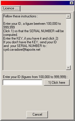
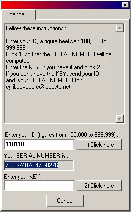
The data reduction software is the executable file called "Sh_analyzer.exe" and can be copied directly from the CD-ROM the the directory you want. This executable file is standalone and does not require any additionnal files. At first startup, the next window will appear : you are prompted to enter your CD_ID (The figure that is written on a sticker on top of the CDROM) , here 110110 for instance, enter it and click "1) Click here" button. Copy and paste the SERIAL NUMBER (7092-7487-2472-8276 in this example) and mail it to me. Then press Cancel. A figure that is called KEY will be sent back to you by email, launch the software and repeat the previous steps and enter the KEY, then click "2) Click here" button. You need a KEY for each PC you intend to use the software, because the serial number will change accordingly. All the information related to this sofware is stored in the database registry : HKEY_CURRENT_USER\Software\Sh_analyzer
Then you're set...
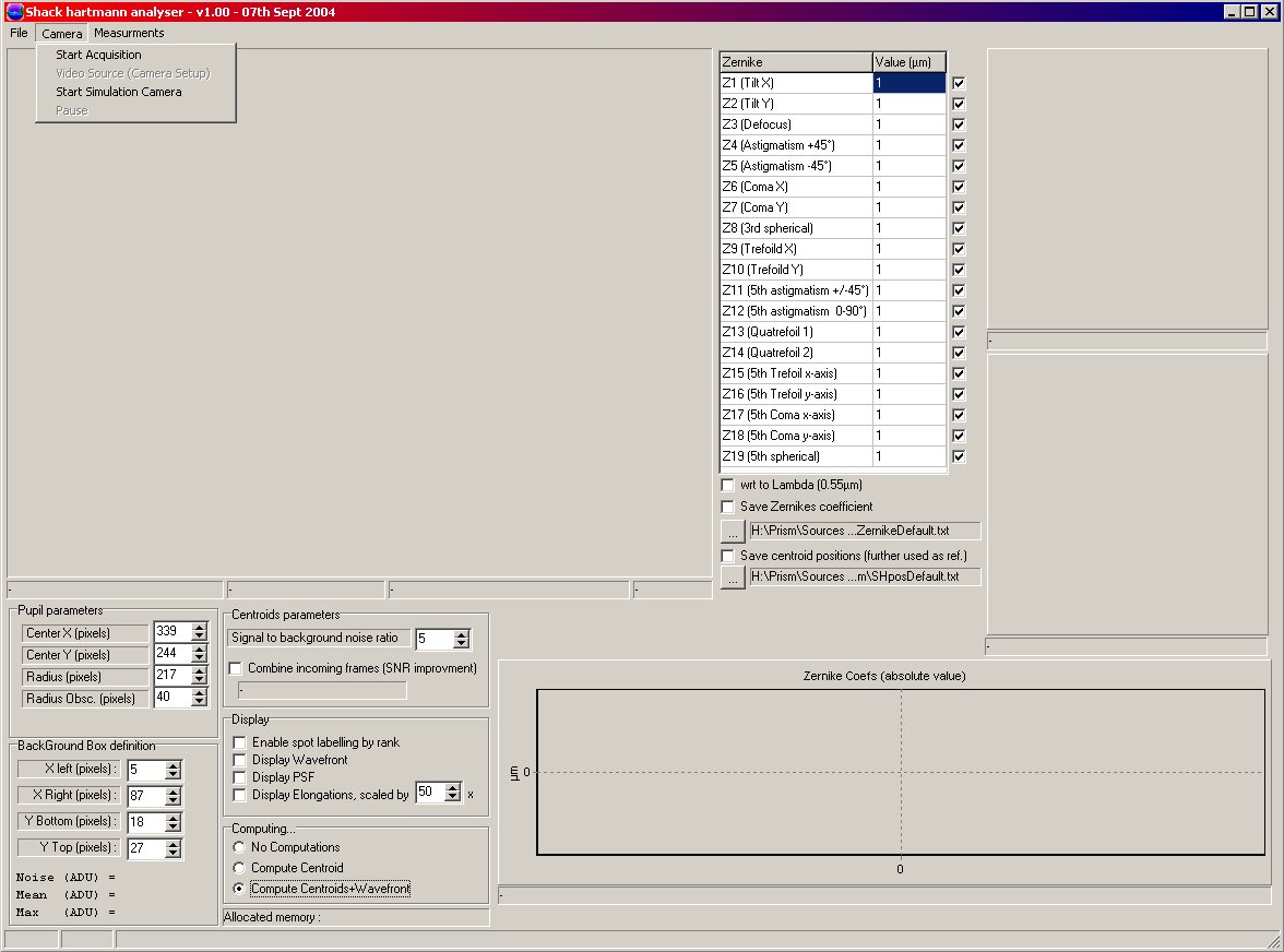
Once the Sh_analyzer.exe software has been launched , this panel appears. 1280x1024 is the minimum resolution to be able to run this software properly. Before Starting, be sure that all the drivers related to the PCVC 740K Webcam have been installed. When using Windows Xp this achieved automatically when connecting the Webcam, otherwise using Windows 2000/ME you need to install the drivers has it is explained into the CD-ROM labeled "ToUCam Pro Philips PC Camera installation Disk".
Then click to "Start Acquisition"
If something fails regarding the driver, this message will pop up.

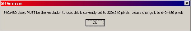
If the camera has a resolution that is not properly set up to 640x480 pixels, then you may get this message :
Once OK is clicked then this window appears, and you MUST set up resolution to 640x480, and compression to I420
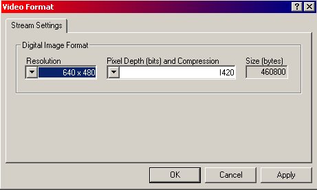
Then Click to "Start Acquisition" again. If the resolution is not set properly the acquisition will not start.
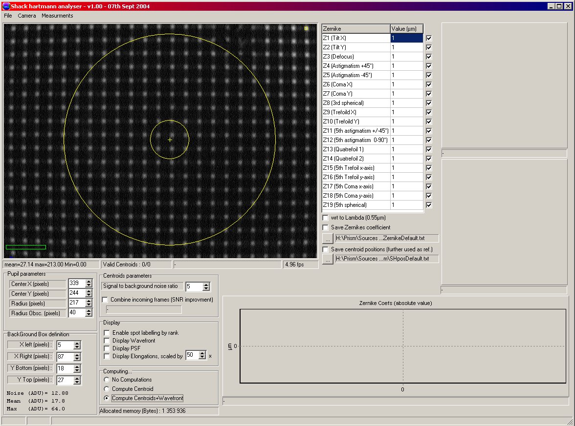
Say, a flat wavefront is provided to the Sh_analyzer, an array of spots can be seen as shown in the next panel... this means that the acquisition is running. ...
The following image has been made using a small pihnole and a collimator (see next page).
At that stage, the camera needs to be setup properly.
Now click to the Menu "Video Source (camera setup)".

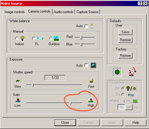
This panel setup the camera acquisition properties. 5 frames per seconds MUST be set when using black and white CCDs, otherwise, you could experience larger errors due to hardwre compression that is used by the camera. Turn on "Black and White" checkbox too. Also, when using the gain "camera control" tab never set the gain to the maximum using Black and White CCDs, leave it as shown hereafter as a maximum if needed, otherwise data compression could be engaged and may jeopardize data : all this features can be noticed while acquiring data.
On every incoming frame the overall statistics are computed and display expressed in ADUs : "mean=25.22 max=230.00 Min=0.00" (red square). The small yellow square indicates the position of the brightest pixel. The highest pixel value is 255 ADU and should never be reached because it would mean that some spots are saturating: this could affect the accuracy of the measurement. In order to avoid saturation either the light level should be changed or the camera setup must be changed.
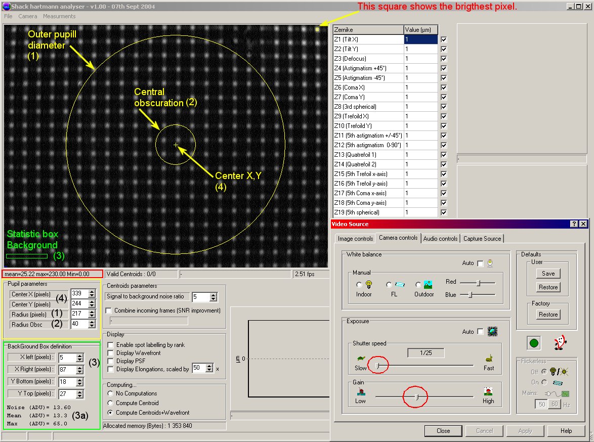
To avoid saturation check the "camera control" tab. And change/tune "shutter speed" track bar (red circle) and/or "Gain" (red circle). The "max" value in the red square should not reach 255. Nevertheless, it should not be too low! 230 +-10 ADU is a good trade off.
The next important step is to set properly the position of the background box ("BackGround Box Definition as green) that computes some statistics outside the spots location. Using the (3) spin edit boxes, the position as shown as a green rectangle into the image can be adjusted, so that to avoid the spots. If this window is not set properly, the computations of the spot reference position may lead to some problems : centroids, spot location.... so this is important to set this box carefully. You should keep it outside the pupil afterwards.
Finally, the yellow items (as (4), (1), (2)) can be adjusted to the future incoming pupil size and position (In the next sections, we will go deeply in details).
Then click to the menu "Measurements/2. System Setup" and enter here the exact value of the "Microlens focal length". Pixel size should be set to 5.6 (µm). Disregard the other parameters, some are duplications from the "pupil parameter" items ((4), (1), (2)) from the main panel group box.
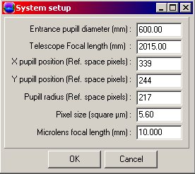
DO NOT FORGET TO ENTER THESE FIGURES !
Now you are ready to carry out the reference measurement position !