
Mount prototype, the engine is a direct drive engine type, located at the bottom left, at the end of the shaft.
French version here - Version francaise ici
Motivations :
Worms and gears use for telescope are :
Direct drive telescope control cancels out all these drawbacks because it is using bushless motors directly mounted into the RA/DEC axis without any additional parts, it is coupled to very accurate encoders (0.015 arcsec per encoder step). Both axis are driven by a closed loop servo system running at 10 Khz. This allow to get very stiff and very responsive axis to the wind.
This technology is employed in modern professional telescopes.
The idea is to migrate toward this technology without using very expensive parts.
Nowadays, this solution is starting to enter the small telescope market because of costs reduction and very good performance parts like encoders and brushless motors....
A demonstrator allowing me to evaluate the way of making this system real and performing according my specification is being presented thru this page.
Integration has been achieved in a modified VMA-200. For the time being, only the RA axis has been modified, the DEC has still a worm and a gear. Since I was starting from scratch, it was too risky to change the two axis at once. This prototype allows me to learn of lot on this topic, even this is just concerning a single axis
Valmeca achieved the mount modifications.
For this time, axis brakes were not installed, but this is expected. It is a feature which we have studied the issues and does not shows any issues to integrate. A loosen type brake when not current is going through a coil is easy to implement.
Mount prototype, the engine is a direct drive engine type, located at the bottom left, at the end of the shaft.

Stator (right) and rotor engine (left), the two are intertwined rings and mounted directly on the RA or DEC axis, the engine is 210 mm in diameter and provides high torque.
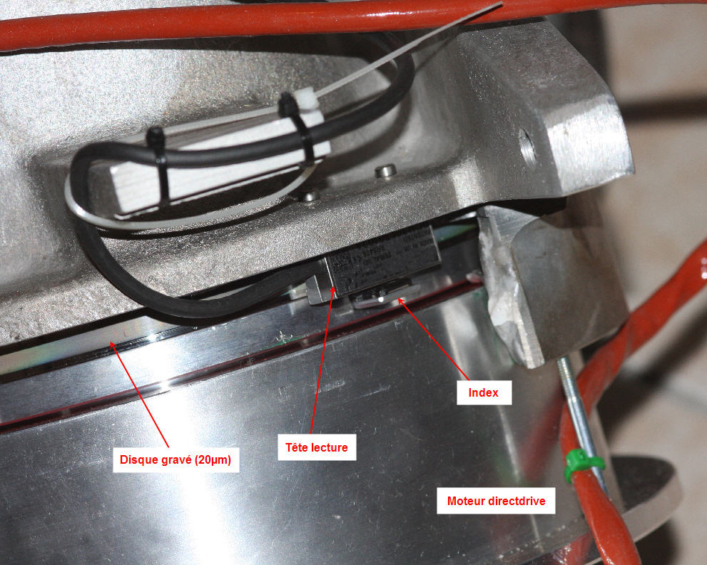
View of the encoder and the read head, it is highly accurate.
As the RA axis has encoder whose resolution is about 0.02 arcsec per steps (nearly 63 million steps per revolution), and it is a closed loop system, it is quite possible to perform indoor tests without stars. This is useful given that good weather is pretty rare in my home place. It also allows fine adjustment of parameters of the PID controller which manages the encoder and motor.
The direct encoder readings provide system performance monitoring.
On the curve below, the RMS tracking error is only 0.05 arcsec, and no periodic error at all can be seen.
Nevertheless, tests shall be performed on sky to validate system performance.
 X axis = Time, Y axis = arcsec time
On February 4th, 2010 first tests on the sky have been carried out.
The tracking regularity was measured with a DMK41AU camera (4.65μm pixel size) using a simple Ø180mm INTES telescope having 1800 mm of focal length.
The pixel scale is about 0.53 "per pixel, this level allows to see any flaws.
The polar alignment shall be careful ... Tube flexure and optical moves shall be avoided at all costs.
One must keep in mind that the encoder is relatively distant (RA bottom axis) from the optical tube.
Bad things can happen from the encoder to the telescope focal plane.
Here is the first plot showing 3 measurement per second during 10 minutes:

The Y scale is expressed in arcsec, and does not show during 10 minutes any periodic error.
The star was located at the celestial equator and the wind was around 10km/h. The curve is noisy because of the tip tilt motion of the star due to the turbulence, the exposure time is 1/400s.
It is interesting to compare this measurement with a gear and worm system, whose performance is relatively poor compared to this DirectDrive system.
There are no comments to add....

This curve look less noisy due to the laying of 2s per point: the effect of tilt tip star turbulence is smoothed.
The yellow area shows where 90% of measured points are located from the DirectDrive system for comparison.
The night of March 4th, 2010 was less turbulent.
The tracking monitoring was measured with DMK41AU camera (4.65μm pixel) using the same Ø180mm INTES equipped this time with a 3x barlow, providing a 5400 mm focal length.
The scale is 0.18 "per pixel: this is a high magnification.
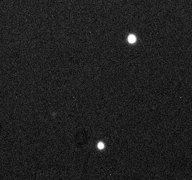
Here is a windowing on the center of the camera, which clearly shows the Airy disk of Arcturus (1/2000s Exposure).
If you click over the image, a DivX video at 15 frames per second will be shown :

The position of the Airy disk is measured 4 times per second, X is RA and Y is DEC: it is possible to show the tracking errors if they exist.
The interest of measuring the DEC axis motion (Y), at the same time as RA motion, is to show that the oscillations due to turbulence are identical, and that the Direct-Drive system does not produce any spurious oscillations on RA axis.
The first RA measurement shows that the standard deviation of the motion is 0.79 arcsec.

The same sequence, DEC axis, shows that this standard deviation is 0.79 "too, so the oscillations of the star have no preferred direction. They are due to turbulence and not due to spurious motion due to the DirectDrive system.

A Fourier spectral analysis on RA axis motion would show any preferred frequency of oscillation:

Spectrum shows only noise, this means that no preferred frequency oscillation is occurring. Certainly a peak at 1.06 arcsec can be seen, but next RA measurement do not show it anymore. There are no RA oscillations due to the direct drive engine system.

If the same FFT plot is carried out with the DEC axis motion data, there are no peak frequency, this is only noise. So the star oscillations are only due to turbulence and the Kolmogorov turbulence statistics and spectrum.

(All these tests were performed with Prism software)
A 180s unguided exposure has been achieved using a DMK 41 camera at a plate scale of 0.53 ":
The stars are round across the RA (X) axis
In what follows, other UNGUIDED tests were performed using a SBIG ST-2000 camera (optimized for deep sky imaging). It has 7.4µm pixel size and lead to a 0.89 "plate scale with 1700 mm focal length.
The polar alignment has been carefully achieved using King method (pole distance of less than one arc-minute), the cables path have been optimized to avoid to pull the camera. The sidereal rate was set as best as possible (731.15 / sec) and a good DEC telescope optical tube balance.
Keep in mind that the best mount in the world will be powerless against tube having a lot of flexure ..... I realize it is difficult to verify these points and may be limiting the system ....
A late night with a seeing between 2 "and 3" arsec seeing was measured. I pointed toward a field near to the celestial equator (DEC ~0 °), who represents the area where errors are most visible (no attenuation by the cosine of the declination).
7 exposures of 5 minutes (300s) have been achieved with this camera and the telescope.
Here are 4 out of the 7 images (X-axis is the RA axis alpha, and Y is DEC)
It is located at RA = 15h30m25s and DEC = 4 ° 00'30"
I could find the coordinates of the field automatically by scanning this region of the sky using Prism software powerfully features.
The results are rather good: the images are sharp, and the elongation of the stars below 20%
The worst is the image 2 which presents an elongation of 27% of stars on the delta axis.
The cause of this defect is unknown.
|
 Image 3 |
 |
 |
 Image 4 |
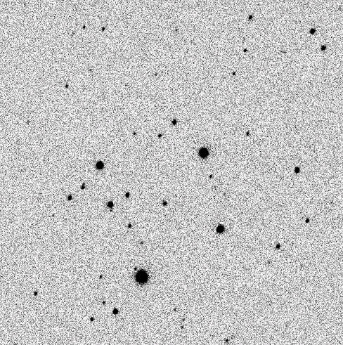 Image 2 |
 |
 |
If you add and stack all images, it lead to a final 35 minutes exposure and the image quality is quite honorable


By adding exposure #1 with exposure # 7 without registration, it is possible to see the difference in RA and DEC over 35 minutes:

The RA offset is 5.1 pixels (4.2 "or 0.12" / min) and the DEC offset is 17.1 pixels (14.3 "or 0.4" / min).
This is probably the combined effects of bad polar alignment and a not perfect sidereal speed (estimated to 0.013%).
But it is still a drift and slow, which is not polluted by any periodic oscillation error.
If a pointing model coupled with an active correction RA/DEC speeds would have been used, the error could be even lower!
In all cases, the periodic errors of worm and gear (see here measurements from many worm and gear equipped mounts) are completely absent.
It has been tested a high speed of 20°/sec, the next video, we started with a 4°/sec speed and going up to a speed of 20°/sec
The power consumption of the system in sidereal rate is about 5 to 10W: no more.

- A 4°/sec speed without the counterweight of 5 kg can be achieved, it's just to test the motor stiffness, it is obviously that this is not a normal operation mode (imagine what can happen if a power current failure would happen). This experiment demonstrates how the axis and its engine are rigid.
Look carefully at the red arrows, they indicate the absence of the counterweight.
Power consumption may increase to more than 100W in this mode.
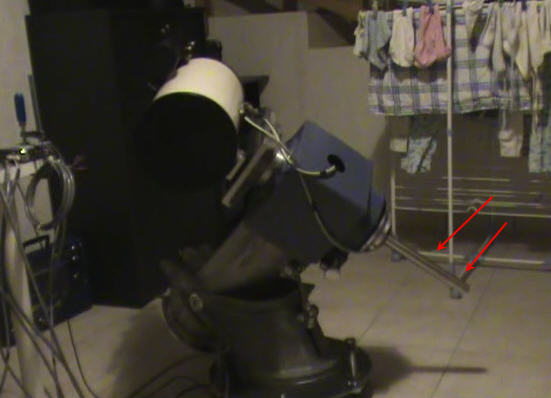
NB: I am sorry for clothes drying in the background ... :-)
