|
|
Even if this mount is branded Konus,
it's
identical to the Kenko NES (including the colors of the knobs!). It's
motorized
in both axes and has an excellent tracking, with a very little periodic
error, considering it's compactness and lightness. It can easily track
15 minutes exposures with a 50mm or more without corrections, always
giving
pin-point stars: this is possible thanks to it's great polar finder. On
the mount I've placed a small acromatic refractor (80 mm f/5) and a
Pentax
75 apo refractor. The first is used as guide telescope and the second
for
deep-sky imaging. With an aluminum bar I can put also two cameras, plus
one piggybacked on Pentax 75 plus one on the counterweight bar. It's an
interesting solution for meteor imaging.
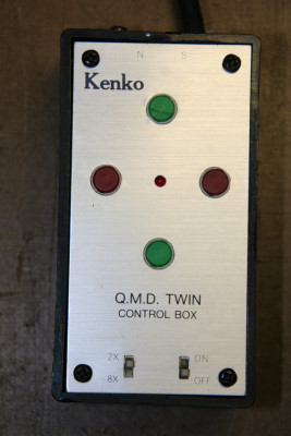
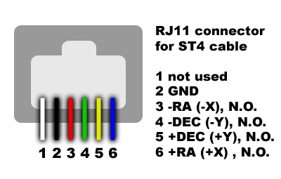
The mount work very well with the ST4,
that I use when I take 40 min exposures with a 200 mm lens or Pentax 75
(500 mm).

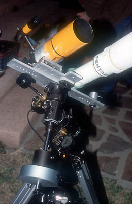

Some views of Kenko
Nes with the Pentax 75 apo and the 80mm f/5 refractor. Note the 6 kg
counterweight
(green): the big overload is well supported by the mount that track
very
well for deepsky imaging.

Graph of the
periodic
error of Kenko NES: it's quite irregular, but the amplitude of the
motion
is however small for such a small mount, about +/-20". Click for
enlarging.
| Hints for
autoconstruction: Discaimer: the reader will assume the risk for all the modifications here propose, moreover the warranty will be void.
|
|
|


 .
.