Fundamental principles of fabrication |
Before launching a project for producing a machine it is essential to list the requirements to make sure its fundamental characteristics meet the mirror maker's expectations. Type of machine : The type will be chosen to answer precise needs.
Capacity of the machine : One must first chose : • the maximum diameter as well as the weight of the glass disk as they have a consequence upon the rigidity of the table and of the structure (mainly such mobile parts as axles, bearings, arms...), the dimensions of the machine and the possibility of setting it up in a particular room, the power of the motors, the devices used to oppose the sideways movements of the mirror on the plate...
• the maximum and minimum thickness of the glass disks (tools and mirrors) in order to determine the bracket of settings for the top disk pin drive. • the number of plates : since for a fixed number of motors the number of rotation plates and cranks may be multiplied their power must be calculated accordingly. |
||||
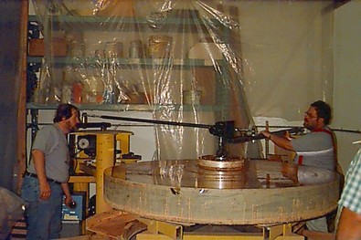
Wide-size polishing machine (built by Group 70) |
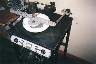
Polishing machine with a double plate (built Mirro-Sphère) |
|||
Practicability : The designing of the machine must also integrate : • an easy access to all controlling and regulating devices : switches, potentiometers, crank-handles, blocks... • simplicity in moving the glass disks : quick and easy dismantling of the driving devices, simple maneuvering of the disks, absence of obstacles, winches... • simplicity of the cleaning operations : smooth surfaces, absence of angles are a plus when cleaning must be done and they limit the risk of grit contamination. |
||||
Example of easy-to-use machine (made by Laurie Hall) |
||||
|
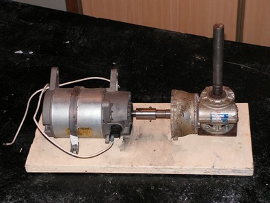
Type and number of motors and speed reducers : Here are the various types of motors with their positive and negative points : • DC motors : Good points : economical, simple and economical systems of speed variation, electrical security. Negative points : usually less powerful, less resistant (wear of electric contacts). • AC motors : Positive points : High power (notably triphase motors). Bad points expensive (notably triphase motors), more complex and expensive system for speed variation, risks of electric shock in a wet environment. • step motors : Good points : extreme variabilty of speed, possibility of computer control, electric security. Bad points : high price, limited power for a moderate price. One must also decide on the number of motors. The ideal solution is to dedicate one motor to each moving element (plate, crank...) because this will limit the risk of recurrent periodical movements that will prevent the creation of regular shapes. Yet, for economic reasons in particular, one single motor may be used to activate various movements through the use of belts and gear-wheels. Speed reducers are mostly gear-wheels systems. They are usually designed to be associated to a precise type of motor (the association being called 'moto-reducer') but it is often posible to connect a reducer coming from the dump to any type of motor. One can also build a speed reducer using pulleys and belts (see next paragraph).
|
||||
DC motor (originally the motor of a washing-machine) with its speed reducer (made by GAP47) |
||||
Speed variation device : Different devices may be used to permit variations of speed : • Pulleys and belts : Advantages: resistant, economical (they can be made or one may get them from other machines). Drawbacks : not very versatile, no progressivity in the variations. • Electrical or electronically-controlled devices : for DC motors one may use variable resistances (but they diminish the motor's power), electronic variators, variable power input, choppers (DC speed controllers) ; for AC motors (monophase or triphase) : variable frequency drives.
|
||||
Belt and pulleys device (built by Juhani Kyyrö) |
Polishing machines fitted with an electronic variator (the red box on the photo) (made by Carl Zambuto)
|
|||
Adjusting the cranks : Different systems may be chosen to perform this task : • Fixing studs on the crank disk, in order to have a series of fixed points for the connection of the arm axis. This system is easy to build but one must stop polishing to modify the setting. • Creating a slide bar : it may consist in just a wooden bar, or a metal bar (square cross-section or U-shaped), or a dovetail bar... The pivot may be blocked in the selected position through the pressure of just one screw. Alternatively, the pivot may be linked to a bolt which is moved along a screw-thread by turning a handle. It is advisable to have the possibility of setting the crank systems to a neutral position (see further down). Adding a measuring device will be a good option to have a precise reading of the offset (scale, gauge...). To set the system to neutral (point zero = no eccentricity) the crank is set in motion and the system is adjusted to the point when one feels no visible back and forth motion.
|
||||
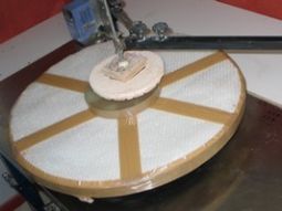
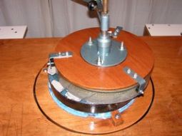
Ways to drive the top disk : Depending on the type of machine and on the type of disk? one may choose from different driving systems : • Drive pin : It is made of a cylinder, preferably rounded at the end or, preferably, of a ball and socket coupling. The pin gets located into a hole in the back of the top disk in order to move it. That hole must be perfectly centered. It may be bored directly into the material of the tool disk (wood, plaster...) but is is more advisable to fit a metal lining into the disk to get better wear resistance (it may be especially machined for the purpose or be a mere metal tube set into the tool). If the connection is not a ball and socket system, the dimension of the hole must be sufficient for the top disk to be free to find a correct position fitting the bottom disk. If the mirror is placed on top, one may consider gluing a wooden or metal block to its back, using the cement used by opticians (pitch + sealing wax). The hole is then bored into that block and carefully centered with regard to the disk. Whatever the solution chosen, the pin (or the ball) must be placed as close to the surface of the disk as possible so as to limit the leverage effect which may lead to the creation of a turned edge, if it is too important. • Alligator : It is a frame that surrounds the glass disk and holds it by its side thanks to side pads. In order to limit stresses to the mirror and let it turn freely, the contact surface must be as small as possible and the pads must be as slippery as they can be (teflon pads, rollers,...). This alligator device is ideal for placing the driving contact as close as possible to the mirror surface, which limits the risks of a rocking effect. Yet it requires a regular shape of the mirror side (circular and vertical). The alligator is mostly used on Hindle-type machines but it may be adapted to other types of machines (see photo below). • Top holder : It will consist of a plate or a star-shaped structure holding side blocking pads. It may be in contact with the back of the disk placed under. In this case it is advisable to place some kind of padding underneath so as to reduce the risk of flexion of the mirror. A ball pin will allow it some freedom of movements to follow the swinging moves of the disk as it slides along the sphere.
|
||||
Turntable : The sturdiness of the structure supporting the turntable will depend on the weight of the elements and the overhang (diameter of the axis, presence of ball-bearings or not, side blockers, ...). In order to lessen the constraints on the axis and its bearing, it is a good idea to let the table be supported by three rollers (placed at 120° angles). The table itself must be perfectly flat, and thick enough not to bend. It must also be water resistant. It will be fitted by side holders (usually three, at 120° angles) which will be adaptable to mirrors of different diameters and will permit a perfect central alignment with reference to the driving center : multi-position studs, sliding holders, cams, threaded shafts... The tip of those holding devices will be made in a material capable of limiting shocks with the sides of the glass disk. The mirror disk will be laid upon a padding layer to avoid flexions (just like at the fixed work station). For thin large mirrors, another good solution will be placing them on supporting points similar to those of the future primary mirror-cell (floating triangles, dynamic levers...)
|
||||
Accessories : Depending on your needs, you may consider using various items that will prove more or less useful : • Container to collect the polishing liquids : Excess liquid that comes out during the polishing session is not usually important. You may nevertheless consider placing a collector under the turntable. • Cover : This accessory may become useful to limit the risks of dust contamination. It may be made out of Plexiglas sheets or consist of a cage covered with a plastic lining. Think of building it large enough to cover the whole machine, including the arms at their widest extensions. Make sure the presence of this cover doesn't lead to excessive temperature inside (remember the nearby motors will give out heat). • Automatic feeder of polishing liquid : For this you'll need a pump (one for aquariums, for instance), a programmer to control the feeding rhythm, an agitator to ensure the product keeps well-mixed, plus an automatic controller to make sure the product is only delivered when the disks are not aligned. • Driving pedal : To control the turntable motor. This is a very useful accessory when working by hand on the turntable. A stop now and then will let you rotate the lower disk without having to change place around the machine. • Rollers to move the machine around : Rollers under the legs of the machine may come in handy. This easy way of moving the machine will be welcome, particularly in a narrow worshop. A valuable improvement will be to choose locking rollers.
|
||||
Machine fitted with a collector (made by Carl Zambuto)
Automatic polishing fluid feeder (built by Carl Zambuto)
|
||||
Centering the movement : A first geometrical adjustment of the machine is necessary to make sure the arm strokes meet the turntable's center of rotation. For this, one replaces the drive pin by a felt pen (in perfect central position) and a sheet of paper is fastened to the turntable (sticky tape, for instance). A white plastic sheet for whiteboards will be a good alternative. To start with, all eccentrics must be set to zero (they mustn't make your finger move when set rotating). Then the felt pen is lead to rest on the paper (no pressure being applied) and the turntable's rotation is started. If the drive pin's axis is not perfectly centered with the turntable there will be a circle forming whose radius will correspond to the distance that must be eliminated. The same technique can be used to get a representation of the drive pin as it is moved by the crank(s) set in motion. This way one can make sure the disk's movements regularly meet the centre or that there is no periodicity in the movement (in which case the loops follow the same path and get superimposed one after another). The glass disk itself must be perfectly centered on the turntable. To check this, the turntable is set rotating and, thanks to a marker or a probe running along the side of the mirror (a piece of wood or a probe indicator), one checks for possible fluctuations. If need be the mirror must be centered more properly by working on the side blocks holding the mirror (avoid complete constraint).
|
||||