How to use a polishing machine : basic principles |
||||||||||||||||||||||||||||||||||||||||||||||||||||||||||||||||||||||||||||||||||||||||||||||||||||||||||
Many different factors come into action when a polishing lap is used to wear away glass. So much so that it is illusory to put this action into an equation. Yet, in order to understand better how optical surfaces are brought to the correct shape we can identify and study different phenomena that take place when "wearing away" glass. The Preston law : That law establishes that the wearing effect is proportional to : • the pressure of the lap on the glass (and vice-versa With a given lap, the pressure, the speed and the time spent are factors that influence the length of the polishing action, but they don't influence the shape obtained. One last factor to consider is the friction coefficient. Its value mainly depends on the nature and the quality of the material the lap is made of (pitch, Polyurethane, Teflon...). It also depends on the polishing liquid (more or less aggressive substance, proportion of water...). Translation and rotation movements : Colonel Charles Dévé contributed a lot to turn the practice of shaping optical surfaces into a theory. We must cite his book " Le travail des verres d'optique de précision", of which we'll only recall some fundamental principles. Two types of movements must be identified : Translation movement : The element considered slides sideways following a trajectory that may be straight (linear) or circular (we then speak of circular translation), or even randomized. This type of movement brings about an action of "even wear" as every spot of the lap leads to the same amount of wear in a given time. This situation is found when we place a lap on the glass disk of a mirror as it rests on the rotating plate of a machine. If the lap doesn't exceed the size of the mirror and if it is moved sideways by a pin which lets it free to rotate, it will follow the same rotating movement as the mirror (at the same speed). There won't be any differential rotation movement between the mirror and the lap. The main differential movement will come from the action of the pin, following a trajectory determined by the stroke chosen. That movement will be a translation movement. In that precise case we'll call the movement a circular translation and every spot of the lap will bring about a similar wear to the mirror.
Rotation movement : In such a case, the element is in rotation if we consider a direction of reference. We are then in a situation of "uneven wear". The wear action by a given spot of the lap is in proportion to its distance to the "instantaneous center of rotation" (see the definition given in C. Dévé's book). Thus, every spot of the lap doesn't bring about the same amount of wear at a given time. This is the situation we find when the lap is prevented from spinning freely around the pin. We get a differential rotation of the lap with reference to the mirror. The situation is the same when the lap, although left free to rotate by the pin, exceeds the side of the mirror. The surface of the lap in this overhanging situation doesn't have a balanced rubbing action of the two opposite halves (which was the case when the lap did not exceed the limits of the disk). Because of this the lap begins to have a slow rotating movement with reference to the mirror.
During polishing and figuring of telescope mirrors the translation movement is generally chosen, because of its overall effect, preferably to the rotation movement, with its non-linear wearing off effect, which is hard to control to obtain a regular shape, free of zonal defects. To that effect the polishing laps will be left free to rotate around the driving pin (thanks to a ball-and-socket joint, for instance). But, as it is impossible to avoid overhanging positions (which are necessary when polishing and figuring) there will be a differential rotation of the lap. Such consequences can largely be limited thanks to the choice of the rotating speed of the revolving plate. That speed will be considerably inferior to the back-and-forth movement created by the eccentric : this way the translation movement becomes more important than the rotation movement and the final effect can be compared to that of an "even wear" configuration. Number of passages : Just as it is for pressure and speed, it is obvious that the wear effect of any given zone of a mirror is all the more important as the polishing lap passes over it more often.
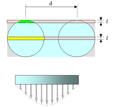
If we now consider the lap's movement over the mirror, it becomes evident that all the spots of it are not equally swept over. The polishing courses, whether by hand or by machine, are all, more or less, back and forth movements across the centre. Consequently the lap will sweep over the centre more often than over the outskirts. This phenomenon is magnified by the fact that the central zones are comparatively smaller in surface than the zones at the outskirts. To be more convincing, let us consider the global surface of a mirror as a juxtaposition of rings of equal width. For any given sweep of the lap, an outwards ring will be proportionately less affected than a central zone, and consequently less rapidly worn away.
Other factors that have an influence over the shape created : Importance of pressing : It is fundamental to start any work session with a careful pressing of the pitch lap, whether hand-polishing or machine-polishing. To that effect, one usually brings the lap to the proper temperature (in warm water or by using an heat lamp), then one must press it over the mirror with a layer of polishing paste in between, plus a good amount of weight on top. When starting a long polishing session it is not essential to press the lap with great accuracy as during work the pitch will naturally get warmer and the lap will soon adapt to the shape of the mirror and quickly eliminate the faults it might have created because of its irregular shape at the beginning. Yet, during the figuring sessions, it becomes impossible to compensate for a faulty pressing as the sessions become much shorter. One must be especially careful when pressing the lap otherwise it will be impossible to master the evolution of the shape. There exists a test to know whether a subdiameter lap is not well-pressed : if you place it over the mirror in an offset position (no overhang !) and you start the rotating plate (the eccentric being at rest) the polishing lap must rotate at the same speed as the mirror if the pressing of the lap is satisfactory. Otherwise you will get a difference of speed or an irregular movement of the lap. It is possible to make this phenomenon more evident if you place pen marks both on the mirror and the lap. When left unused for a long time, a lap will lose its shape : the pitch squares will melt down and become convex. This is even more important if the lap is stored in a warm room (mainly in summer). In that case it is advisable to keep it in a refrigerator (which also reduces the evaporation of solvents). It is necessary to press the lap for a long time if its squares have seriously lost their shape, but if you conduct frequent polishing sessions the shape of the lap will remain rather stable : it is then only necessary to cold-press it for a few minutes before each session.
Quality of the pitch : The physical qualities of the pitch used play a fundamental part in a lap's capacity to produce a quality job that is adapted to the characteristics of the optical object to polish or to figure. Its plasticity depends on different factors :
When working on a regular spherical shape, a harder type of pitch will be more adapted during polishing. It is the same when figuring a slow mirror. A smoother pitch must be chosen for the figuring phase of a fast mirror. Indeed, in such a case, a smoother lap will have a greater capacity for dealing with the differences of curve radius when moving over a fast parabola. For this reason, it is particularly difficult to bring correction to the outside zones of a very open parabola, if you use a somewhat hard lap. Once convinced of how important pitch firmness is, you still have to assess the degree of hardness and compare it to an established standard. To that effect you must use a hardness tester (a static penetrometer, for instance) the tip of which consists in a pointed cone, or a ball, or even a small-diameter cylinder with a flat end (see the page dedicated to pitch testing). Finally, we are going to recall some basic principles one must respect in order to make a good use of a pitch polishing lap :
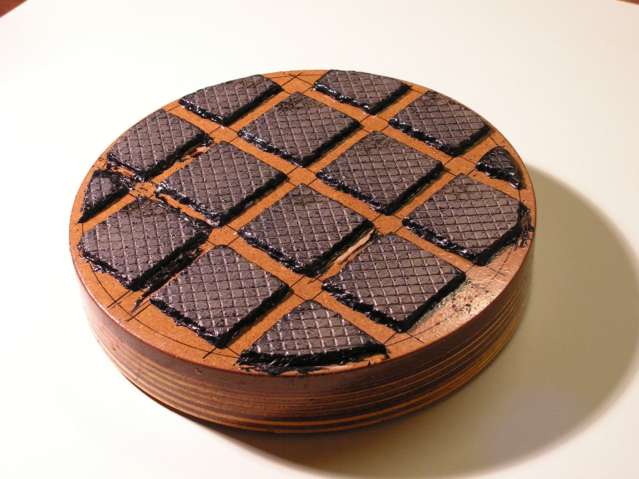
Now how about the grip ? Glazed pitch squares are badly adapted to machine polishing. As a matter of fact, their contact is too "hard" and not homogeneous enough which leads to chaotic movements of the lap and to zonal faults through edge effect (see the video clip below). To improve the grip, one must "stamp" the surface of the squares, whether by using the tip of a cutter blade (regularly spaced grooves) or by pressing a mesh over the squares (a 5x5mm plastic mesh, for instance). To complete this action, Carl Zambutto finely scratches the surface of the squares using a brass brush (with thin stainless blades). It sometimes leads to a complete scrubbing of the crusted surface of the squares embedded by polishing agents. Pressing a mosquito net is another option. Those actions are often called " micro-faceting". Laps prepared with these techniques bring about a better flow of the polishing product as well as a more regular temperature of it. The lap/mirror contact gets smoother and more even, leading to a better action of the laps.
|
||||||||||||||||||||||||||||||||||||||||||||||||||||||||||||||||||||||||||||||||||||||||||||||||||||||||||
How to position the disks : Figuring a large mirror is mostly done with the mirror below. There are various reasons for that :
Yet, it is sometimes interesting to alternate work with the mirror on top and the mirror under a full-size lap : to accelerate the elimination of the grayness in the centre of the mirror, to smoothen out the shape or to bring correction to a zone (the centre for instance). |
||||||||||||||||||||||||||||||||||||||||||||||||||||||||||||||||||||||||||||||||||||||||||||||||||||||||||
Supporting the mirror : One must keep reminding one notion : A high quality in the making of the mirror's support is fundamental to avoid any risk of astigmatism, or at least keep it within tolerable limits. Allow us to repeat some of the most essential precautions one must take in this respect :
Every 15 to 20 minutes, turn the mirror a little less than a quarter turn on the stand.
|
||||||||||||||||||||||||||||||||||||||||||||||||||||||||||||||||||||||||||||||||||||||||||||||||||||||||||
General principles in how to use a polishing machine : |
||||||||||||||||||||||||||||||||||||||||||||||||||||||||||||||||||||||||||||||||||||||||||||||||||||||||||
Size of the laps - length of the strokes : The method followed for the figuring of a mirror with the help of a machine consists in the use of a collection of polishing laps of various diameters, smaller than the mirror's diameter (they are called "subdiameter laps"). The larger the lap the greater and the more homogenous the extension of its action. On the opposite, a smaller lap will be used to "deepen" more limited areas. As a rule, one uses a collection of laps of about 60%, 50%, 40% and 30% of the mirror's diameter, and this is sufficient for most mirrors. Yet, in the case of larger mirrors or faster mirrors other sizes may prove useful. Besides, the length of the strokes allows us concentrate the action on any precise zone of the mirror : long strokes will reach over large zones of the mirror whereas shorter strokes will aim at narrower zones. A good combination of lap diameter and length of stroke will decide what precise zone we are going to bring correction to. For instance :
|
||||||||||||||||||||||||||||||||||||||||||||||||||||||||||||||||||||||||||||||||||||||||||||||||||||||||||
To make a long story short, it is always the centre that is the aim of the action but over a variable extent of surface, according to what surfaces are to be corrected (close to the centre or away from it), using tools of different sizes. |
||||||||||||||||||||||||||||||||||||||||||||||||||||||||||||||||||||||||||||||||||||||||||||||||||||||||||
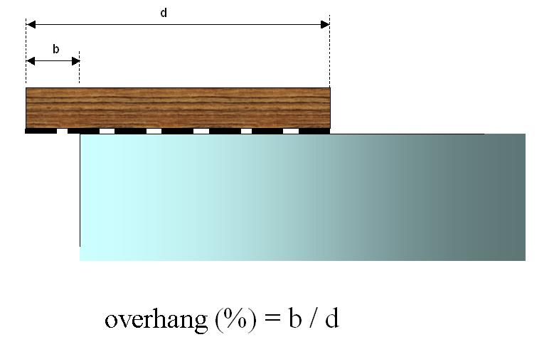
What are overhangs : An overhang is the part of the lap that exceeds the edge of the mirror at the end of a stroke. It is usually given as a percentage of the lap's diameter (i.e. : a 50 mm overhang with a 200 mm lap makes a 25% overhang). The back and forth movement created by the rotation of the eccentric must be set so as to get even overhangs on either sides of the mirror. Increasing overhangs will bring more correction to the outside zones. Be careful not to use excessive overhangs as this will lead to turned-down edge. |
||||||||||||||||||||||||||||||||||||||||||||||||||||||||||||||||||||||||||||||||||||||||||||||||||||||||||
|
||||||||||||||||||||||||||||||||||||||||||||||||||||||||||||||||||||||||||||||||||||||||||||||||||||||||||
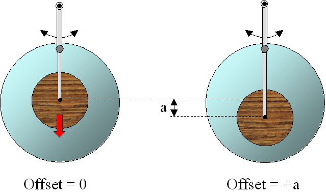
How offset settings work : Setting an offset is a way to place the centre of the strokes away from the turntable's (and the mirror's) centre of rotation. Thus, the centre of the lap (which corresponds to the zone where rubbing is most efficient) will slide outwards and bring correction off centre. The offset effect helps bring correction from the central zones towards the edge.
Frequent changes of the offset help getting a smooth shape as well as avoid zonal faults that are easily created by an excessive repetition of the same movement. Besides, using offsets is a way to increase the job done by a lap, as if its diameter were "inflated". This technique is a solution to avoid multiplying the number of laps one needs to correct each zone. One can easily see that using offset settings is fundamental when machine-figuring a mirror. The different parts composing the offset machinery will have to be precise and efficient. We insist on the importance of the principles applied when building a polishing machine. This will ensure efficient settings of the offset, leading to even overhangs (see the chapter dedicated to machine building). Why use a second eccentric : Some machines are built with two eccentrics. The main eccentric is used to give their length to the strokes. The second one is simply there to add some random effect to the main movement : this is called "randomisation". For this, its radius must be limited to a mere 1 or 2 cm, so as not to transform the overall shape of the strokes created by the first eccentric. Whenever one reduces the length of the strokes, the values of the second eccentric must be reduced as it mustn't become prevalent in the global movement. In some circumstances it is useful to bring its value to zero (eliminating its action completely), to ensure a fixed overhang and aim at precisely bringing correction to a given zone, or centre the strokes to rub down the centre more rapidly. Pressures to be applied : It is usually possible to add weights to the machine's arm in order to increase the pressure applied by the lap. How much pressure to apply depends on what phase of the work we have reached :
Let us give some examples of such weights for each phase of the work : Polishing phase : when using a pitch lap, one may work with pressures ranging from 50 gr. per cm² at the start down to 15 gr. per cm² towards the end in order to improve the aspect of the mirror's surface. With a polyurethane lap one may apply pressures as high as 200 gr. per cm². Please, note that the above pressures have been calculated with the actual surface of pitch in contact with the glass. To know these values one can use the following spreadsheet :
Specific methods : Using a full-size lap : When working on a machine, it is difficult to use the method developed by Jean Texereau for the figuring of "small" mirrors with the help of a full-size lap. Indeed :
But, in some cases, using a full-size lap on a machine may have its good sides :
|
||||||||||||||||||||||||||||||||||||||||||||||||||||||||||||||||||||||||||||||||||||||||||||||||||||||||||
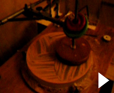
Machine polishing on a double-crank machine (with limited strokes and speed). Click to see the video clip |
||||||||||||||||||||||||||||||||||||||||||||||||||||||||||||||||||||||||||||||||||||||||||||||||||||||||||
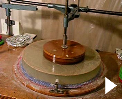
The "centre to edge" method using a half-size lap : This method is slightly different from Carl Zambuto's although it appeals to the same properties of the lap (adaptation of dimensions and overhangs to the zone to be corrected). Yet the logics used here work in a reversed manner : the progression is driven from the centre towards the edge. Thus the first step will consist in deepening the centre with the help of a small-diameter lap (30 to 40%). The pressures applied must be moderate so as to avoid too fast a correction and the creation of dog biscuit. Then, using a 50% lap together with wider strokes, the correction is extended outwards until the zone aimed at has been reached, not unlike a "wave" progressing towards the coast (see the clip below). This type of work is conducted by series of slight corrections until it has modified the zone that needed correction in the first place. For the implementation of a progressive correction outwards one will make use of offset settings. A 50% lap will bring steeper correction slopes than a 60% lap. This "aggressiveness" makes it more adapted for figuring fast mirrors. It is possible to use this method, as a complement to Carl Zambuto's, especially for fast mirrors (mirrors with a faint F/D ratio).
Strategic practical tips for figuring : Starting the figuring action : Figuring should never be started before the general shape of the mirror has attained a reasonable homogenous aspect : limited zonal faults, no turned down edge (or, less frequently, turned up edge) and astigmatism, above all. A slight general correction is not a bad idea, far from it, if it is smooth and regular. To get a good view of the situation, it is advisable to have a look at the general shape through a Foucault tester or through a Ronchi grating. If need be, one can even take some longitudinal measurements of the zone that seem most doubtful to you. In order to smoothe a slightly zoned shape before actually starting figuring, one can use a 60% lap with wide strokes (reaching 25% overhangs). At the end of the first figuring sessions, the measurements made are rough, measuring the overall difference between centre and edge, for instance, using a Foucault tester. As for judging the smoothness of the shape and the absence of zonal faults, this can be done with a Ronchy test or Fresnel bands. General strategy of work : As figuring advances it becomes more and more important to have a more rigorous method in taking measurements and deciding corrections. It will also be important to keep a corrections notebook made in order to follow their history and be able to understand their efficiency better.
|
||||||||||||||||||||||||||||||||||||||||||||||||||||||||||||||||||||||||||||||||||||||||||||||||||||||||||
To take measurements one uses a Couder screen. It is important to wait for at least an hour (better two) between cleaning the mirror and taking measurements if you want to be sure the mirror has reached its thermal stability. It will be advisable to take two series of measurements so as to increase the final accuracy. The closer one gets to the end the more rigorous one has to be as far as thermal equilibrium and measurement accuracy are concerned. As for the corrections notebook, the more details it holds the easier conclusions can be drawn from it, understanding the relations between actions and results. We think it a good idea to develop a few written comments about how to analyse the outcome of a correction and what to choose to do afterwards. Visually representing those measurements and their progression through a graph can be done by a method we find well adapted to the job of machine-figuring a mirror : One must first calculate the theoretical longitudinal aberrations values of an ideal parabola for each zone of the Couder screen. Then, one computes the differences between values belonging to neighbouring zones. Here is a concrete example to make this explanation clear (corresponding to an F/D 5, 300 mm mirror) :
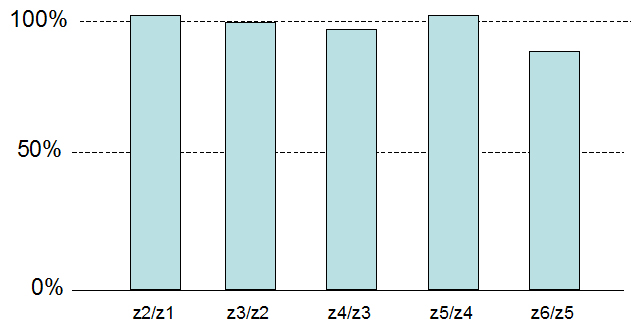
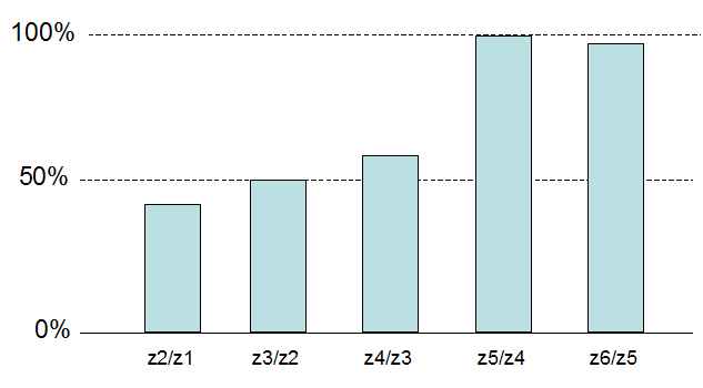
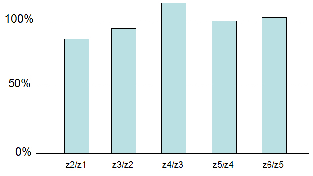
Next, one takes the actual measurements and one compares the differences between zones to the ideal values computed before, the comparison being expressed in percentages :
A histogram graph helps get a better view of how corrections are progressing :
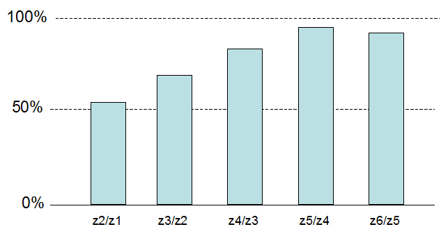
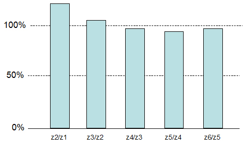
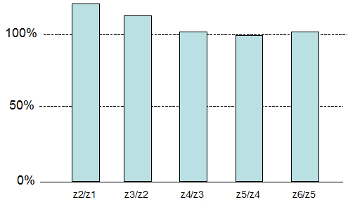
As a consequence a perfect parabola will be represented in the graph by a series of identical bars reaching the 100% mark. The same type of graph will prove useful to visualise the progression of the corrections obtained between two sessions. The strategy to follow while figuring a mirror will consist in having these bars progress in a regular and homogenous way : At the start, the progression for some of the bars will reach progressions of up to 10 or 20% between sessions, without any risk. Towards the end it will be wise to limit progressions to a few percents to ensure a "safe landing". At that stage it is advisable to work by series of short sessions instead of trying to reach the final result immediately, running the risk of over-reaching the aim of 100% on some zones. It is indeed often difficult to salvage a correction that has gone over the required value. This is especially true for the outside zone that is impossible to save through classical corrections. It is prudent to keep a little margin on that zone and wait for the final stages to "push" it to the 100% value. Besides, one must be careful to bring homogenous progression to all the zones. It is important not to let one zone progress too quickly when compared to the others : ideally, any advance between two neighbouring zones should be kept within 10 %. While working along the previous principles, Carl Zambuto suggests pushing the outside zones a little ahead the central zones. According to that method an ideal progression of the bars in the graph will be as follows :
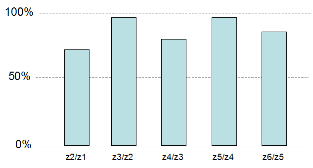
In spite of all the precautions taken, some zones may get too far ahead the others or progress without a general continuity. It is then important to bring the corrections needed in order to give the histogram a smooth profile, devoid of overcorrected zones. The general method for these corrections of the profile will be to aim at precise zones to increase correction there, or, on the opposite, to reduce it. All the devices present on the machine will be put to use : lap sizes, overhangs, offsets, importance of the strokes, nature of the strokes (brush stroke, sweep technique). The following chart gives a description of some of the most frequent correction actions :
(*) For fast mirrors (with small F/D ratios), the large 60% lap will be dropped to be replaced by a 50% lap, which will be more aggressive. As for overhangs they will be allowed to exceed the 30% usual limit. One very efficient correction method may be put forward too. It consists in centering a lap precisely over a crest and giving it tangential strokes. This way of correcting is shown in the clips below :
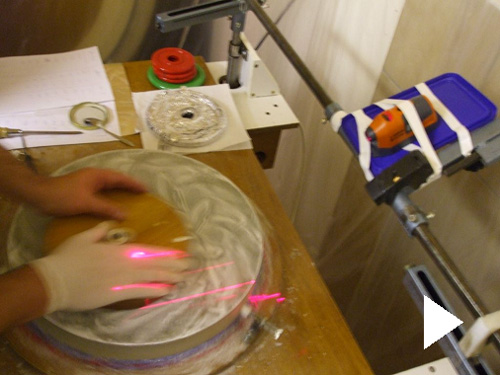
In that precise instance the aim is to lower the crest formed by the slopes in zone 3 and zone 4. The tangential stroke moves the centre of the lap from the middle of zone 3 to the middle of zone 4. The lap's top efficiency is most important at its centre, consequently the number of times it sweeps over the crest will eventually level it down. The surface of zone 3 being inferior to that of zone 4, it will tend to get more correction (the rubbing effect will tend to be more important there). To avoid that one will limit the importance of the movement over zone 3 (on the inward side of the crest) laying more stress on the outward side (zone 4). To that end offset settings will be used and this will improve the blending of the zones. Yet there is a dark side to that method and we must point at it. Reducing the slopes on either side of the crest means transferring correction to the zones on either side of it. If those zones are already well ahead towards the final target the correction brought to them may create over-correction. What lap diameter to choose is linked to how wide the crest is. A small lap will bring correction to a limited zone, it will work quicker and have a sharper action. Such an aggressive tool may create zonal faults and/or dog biscuit. Knowing that, it is advisable to launch a smoothing session immediately after, using a larger lap and the same type of strokes. In the end, it is worth speaking about extra pressure corrections as described by Jean Texereau. Their very limited surface may help get out of a deadlock that a machine-only work could not solve. Although this type of work is done by hand, the use of a machine can bring comfort to the performance. To that end, the machine's turntable is used to give the mirror a constant rotation (at a slow speed of about 3 rev. per minute). To help focusing on the precise zone to correct it may be handy to use a laser beam. Think of printing a mark on the table to make sure each correcting session is composed of full rotations. The video clip below shows an example of this type of suppressive correction on a revolving turntable :
End of figuring : The final stages of figuring must be completed smoothly to get a good surface finish and quietly reach the best possible corrections :
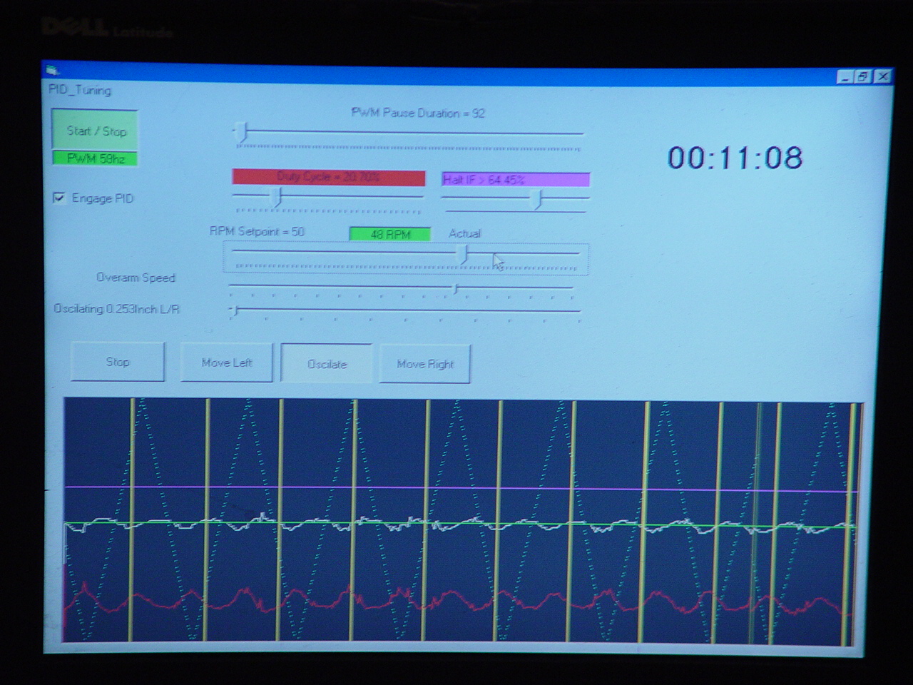
During the last sessions corrections will be applied through delicate precise actions and short times of action. The mesh print on the lap may create some slight echoing the structure of the mesh used at the time of pressing the lap. The elimination of that microroughness will have to be done during the final figuring phases. To that end one will press the pitch squares of the lap so as to completely erase the prints at their surface. Then a series of slow strokes will be performed, using a rather thick polishing liquid. Finally, the end of the figuring process will be followed by precise measurements. To reach that precision the measurements will be taken along two meridians at least, after letting the mirror rest a sufficient period of time (some hours will be a good amount). At that stage the mere graph showing the progression of the correction work won't be considered as sufficient. It will be wise to complete this analysis with a graph showing the wave profile, and another one showing the reduced transverse aberration. Using softwares : A computer can be a useful tool when machine-figuring a mirror. It may be used more or less extensively : Automatic piloting of the machine : Up to now, all the projects of robotization of a polishing machine have remained extremely confidential among the ATM community. Yet, some experiments seem to be under way inside the ComputerizedMirrorMaking forum. One should also point at James Lerch's research on the wearing off phenomenon and the computerized control of a machine :
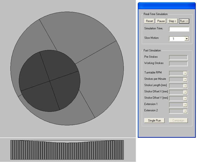
Some type of automation may contribute to the randomization of strokes and help make the various setting changes smoother and more progressive. One can also imagine an automat will be able to "learn the job" to a certain extent by stocking the results obtained with such or such setting in a precise configuration of the machine. Yet one must remain reasonably enthusiastic : machine figuring a mirror in a fully automatic process, the operator just pressing a button to get the perfect mirror, is a complete dream. Whatever happens, an operator's experience and reactivity will remain essential to ensure a full success to the job. Simulating the wear profile : Besides James Lerch' works, we can recommend Polsim software, developed by Martin Cibulski :
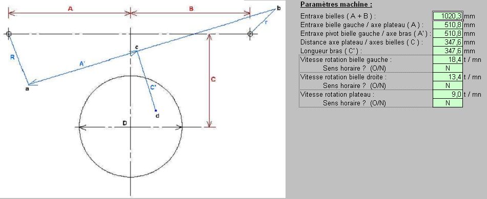
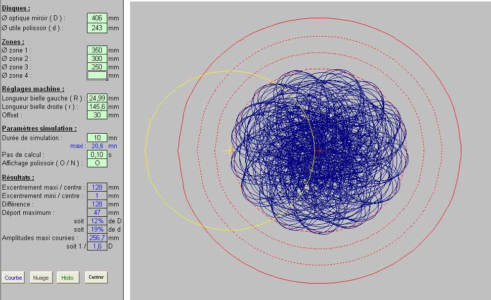
Helping select settings : When comes the time to determine what strokes and overhangs to associate to such or such eccentric or offset setting one may choose to simulate these actions directly on the machine. Yet, it is much easier and quicker to have these simulations through a software which will let you indicate what type of machine you're using, the size of the lap, the importance of the strokes, the value of the offset... That way you quickly obtain the importance of the overhangs. You can also get an idea of the possible inconsistencies in the succession of strokes. Here are some screen shots taken from such a tool, using an Excel basis. They show how useful that sort of tool may be (Draper-type machine with offset arm) :
Download spreadsheet for each type of machine : Draper-type machine with offset arm : click to download (18 Mo) Zeiss-type machine : click to download (13 Mo) Warning : These calculation sheets contain macros. To have them work properly they must be activated on opening the sheet, or select a low security level.
|
||||||||||||||||||||||||||||||||||||||||||||||||||||||||||||||||||||||||||||||||||||||||||||||||||||||||||