|
|
Cookbook 211 Autoguider
Guiding allows long exposures with film or CCD camera. While reasonable CCD images can be assembled by stacking numerous short exposures, a few longer ones will let you detect significantly fainter objects. For example, a single 240 sec. exposure has better signal-to-noise characteristics than a stack of 64 (!) 30 sec. exposures (which went through 64 read-outs).
Manual guiding is the easiest way to keep telescope drive errors from spoiling your images. However, it is tenuous and eventually you end up supporting your local chiropractor a lot. Autoguiding is the "sane" solution - you can observe night sky visually while exposures are automatically guided or go back inside and watch a movie. After all, taking a number of 4 or 10 min. exposures and stacking them will result in even deeper image!
I have built Coocbook 211 CCD camera for use as a dedicated autoguider. Camera itself was built exactly as described in "The CCD Camera Cookbook" by Berry, Kanto and Munger (also, see Cookbook webpage). My camera includes LDC (low dark current) modification (Wilmann-Bell).
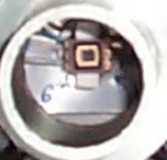
Images below show the overall view of CCD head and interface card box as well as offer a peak inside to reveal TI211 CCD chip. While it is tiny (about 2.5mm x 2.5mm and 192 x 165 pixels), that is more than enough to find a star (just a bright point, afterall). Because Cookbook 211 is cooled to below -30°C, guiding on stars down to 12 mag. is easy even with my small guidescope (60 mm aperture).
|
|
Cookbook 211 connects to an old 386 computer running 211Plus software written by Richard Berry. Its autoguiding function measures shifts in a guidestar position and sends corresponding signals to telescope drive. One additional piece of hardware needed is an autoguider card described at Cookbook webpage as well. While I am using Celestron Ultima 8 PEC Schmidt-Cassegrain, the circuit described for LX200 works perfectly well with Celestron mount. All components were mounted on a perforated board. While 74LS06 IC was used originally, I later replaced it with relays. Card is powered directly from internal computer power supply (there are usually spare connetors available there). Drive correction signals arriving from serial port activate relevant relays which in turn are connected to telescope drive with 6-connector telephone cable.
Activation of a particular relay shorts corresponding pins in telescope drive as listed below. Pins are numbered from left to right when looking down at telescope base.
pin 3 to pin 2 - Fast RA
pin 4 to pin 2 - DEC up
pin 5 to pin 2 - DEC downz
pin 6 to pin 2 - Slow RA
pin 3 to pin 1 - focus / mirror forward
pin 4 to pin 1 - focus / mirror back


Number of visitors:
© Jan Wisniewski