|
|
|
The design and building of a large dish antenna rotor
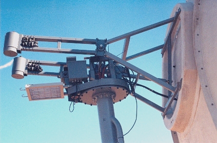
Text and pictures by Cliff Bates, KC7PPM The project (II) I live in the center of Washington State. The weather here is variable.That is, it has gone down to -25°F (-32°C) below in the winter, and up to110°F (+43°C) in the summer. Winds here are a problem 3 to 4 months of the year. My house is on the hillside of a valley, and probably 4 to 5 times a year the winds get to 85+ mph (137 km/h). The reason I say + is because the wind speed indicator only goes to 85 pmh. This is not a good location for a large dish. Down in the valley this same wind is about 35 mph (56 km/h). Snows here can get pretty bad, but with global warming the snow seems to be moderating as the polar ice caps depart. The reason I mention this is, you should consider what kind of weather you live in before you build a large dish. In short, can your pocket book and the resulting dish, stand up to the elements Don’t just design for the average weather conditions, “design for the worst”! Eventually Mother Nature will attempt to destroy your dish. Usually when your at work, asleep, or on vacation. If you go to all the trouble to build it, protect that substantial investment in time, labor, and money, with something designed to meet the weather in your area. Obviously you can’t design against hurricanes, or tornadoes. That is a risk you’ll have to live with. However you can design against thunderstorms, which is the single most dangerous threat your dish may have to contend with. High winds, heavy rain, lightning, hail, all balled up in one big event. Movements of the dish The next thing I decided to look into was how to move the dish. Actually I considered at one point in putting the dish in the ground, like Aricebo, but decided against it because the tracking ability was to limiting for my latitude, as well as the other things I wanted to do with it. I also decided against a dish with no azimuth control. At Green Bank the 40 footer (12 m) is made available to the SARA members at the yearly gathering, if it is not being used for research. It is a “very fine top of the line” instrument, recently updated with new equipment. However it has no azimuth, (horizontal) movement capability, only declination (elevation). This solves many structural and movement problems involved in building of the dish. But it also imposes some severe restrictions on the freedom to point the dish about the heavens at will. I quickly found out that if I hadn’t anticipated everything I had to do in recording an observation with the 40 footer, I had to wait until the next night for another attempt. Or if something really interesting caught my attention, I couldn’t continue to track it. So I figured that if I was going to go to all the trouble of building a bigger dish, then it shouldn’t be limited by its movement in what it could do. The mount and the rotor How to mount the dish came next. In searching the Web there were many photographs of various large amateur dishes.Some to up 45 feet (13.5 m) in diameter. Others mounted on 5 inch gun mounts! It is absolutely amazing at what people can come up with to solve a problem when the need arises, and they are determined. I liked the circular track idea for azimuth control. I still like it. A dish mounted between two “A” frames on trucks, (wheels) riding on a circular track is a very strong structure. It has the advantage of being able to handle the wind loading better. Plus it is easier to work on and maintain than a pole structure with the rotor sat on top. Access to the horn, preamp, receiver, waveguides, position indicators, or encoders is easier and safer. Weight is carried by the trucks, not on a thrust bearing. Then there is the falling distance to the ground of the person working on it is usually less, which is nice benefit. On the negative side, the track area takes up a considerable amount of ground space. In areas with snow considerations, keeping the tracks cleared of snow and free of ice can be a problem. An absolute must is a level circular track, and this can be the most serious problem to overcome. Cabling up waveguides and power to follow the structure as it rotates can lead to some interesting problems as well. Yet building the observation shack inside the support structure for the dish, and having everything go around with it would be an interesting solution to several problems.
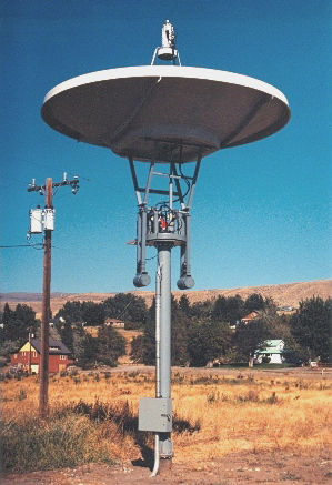
The pole mounted rotor seems to be the most popular, even though it has many disadvantages over the “A” frame on a track. Its most practical advantage is space savings. The second advantage is simplicity of the structure. A large heavy wall pipe being much easier to place and build than a “very level” circular track carrying an “A” frame structure. On the negative side the pole has several disadvantages.It is an advantage over an “A” frame up to a certain size of dish. Beyond that certain size, determined by the dishes weight, its area, support pole diameter,weather condition factors, rotor weight, access convenience for maintenance, etc., the pole mounts simplicity begins to rapidly disappear. Not to be forgotten is the foundation block to hold the pole up.This MUST be at least equal to the force of the designed wind loading. Or like the old sailing ships, the dish will roll over. Also the lack of stiffness in the pole can be felt not only when your up working on the system in a mild breeze, but also in the recorded observations on the chart. A larger diameter pole, equals a stiffer pole and better observations. After completing my dish and testing it with a sun shot. I thought I had an electrical short in something. The wind was blowing about 10 mph (16 km/h), and the chart was showing a wavering in the signal that shouldn’t have been there. I finally noticed that the TV camera I had mounted at the back of the horn, to track the sun, was weaving around about a half of the suns disk instead of staying centered during the test. Consequently the signal was wavering as the dish was moved around by the wind. I finally decided on a pole mounted dish. The choice of a pole over a “A” frame was made mostly due to space considerations. I built the large dish next to my original setup for the 10 foot (3 m) dish and shack. It was located down in the valley in a friends apple orchard.My friend requested that the new dish lip be at least 7 feet (~2 m) off the ground when the dish was lowered down so he could move his orchard equipment under it without hitting the dish. Also a cleared area for a circular track for an “A” frame structure he politely hinted, would have cost to many apple trees, that were more income producing than a RA dish. To survive the wind loading I used a 10 inch pipe with a wall thickness of 3/8ths of inch thick, 17 feet (5.1 m) long. This had two flanges welded on each end. One end was bolted to the rotor support disk, the other end was bolted to another 7 feet (~2 m) of the same pipe size, with another welded flange, with fins welded on the piping that was to be cemented into 35,000 lbs (15.8 ton) of poured concrete. Where I worked was an old civil engineer who was also interested in my endeavor offered some engineering suggestions on the pole size, and base mounting. One of his suggestions was to use fiberglass concrete for the base, to resist cracking. Another was to weld five 2 ½” by 5/16" by 5 foot long fins on the pipe that was to go in the concrete to assure that the pole, through heat expansion and contraction, did not loosen in the concrete and rotate. The fins would also distribute the forces out into the concrete better than just the plain round surface area of the pipe. At the base of the pole that connected to the pipe foundation he suggested putting another 5 tapered fins, 1/4" (6 mm) in thickness, tapered from one inch to 2" (5 cm) at the flange end, 10" (25 cm) long, and then welding them to the pipe and flange surface to again spread the forces on the pole out along the pole pipe, rather than concentrating it at the joint where the pole flange connected to the one in the concrete. He also suggested not to taper the hole for the concrete, but to keep the hole sides straight to resist the toppling forces on the pole.As he said, shallow rooted trees topple easier than trees with tap roots. Here are a few cost considerations (in 2002 US$) on the pole and foundation. Three 10" pipe flanges, $150 each. 25 feet of 10", 3/8 walled pipe, $225. 24 - 3/4" bolts, $1 each.Washers, both sides, 50 cents each. Nuts for the same, $1 each.7 yds (~7 m) of fiberglass concrete, $500. Backhoe to dig hole, $65.
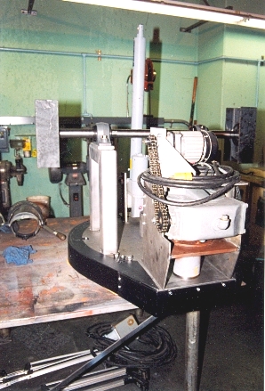
Finding a cheap dish The size of the dish, and what it was to be made out of, kind of solved itself. After looking on the web for dishes, I found one 24 foot (7.2 m) satellite dish made of perforated sheet metal. I called and received a quote of approximately $6,000. This included the post, stand, and the horn. None of which I would use. I could not buy the dish by itself. I looked at some 16 foot (4.8 m) fiberglass dishes that were nicely made, and broke down into 3 pieces for shipping. These turned out to be $15,000. Shipping was extra. I decided to see what the local satellite dish dealer had. Same stuff, same price. But as I was walking out the dealer asked what in the world I wanted that big a dish for ? I told him, and he said, “I think I have just what your looking for in a 15 foot (4.5 m) dish I’ve had in storage for 20 years, and never could sell”. Out in the storage yard was what appeared to be a AFC, 15 feet (4.5 m), “C” and “K” band fixed mount fiberglass dish. It broke down into 3 pieces, and had a very accurate surface. It also looked like it was built to withstand a nuclear blast. It weighed in at 850 lbs (385 kg) without the mount ! He said, “It’s yours for $300". I said, “I’ll give you $400 for it, the $100 extra is for a years storage fee until I get the rotor mount made”.We both rushed to the cash register before the other guy could change his mind! The dish was smaller than I really wanted, and weighed more than a metal 24 footer (7.2 m) by far, but it’s design solved several problems. One of which was mounting it to the rotor system.This thing had no metal bracing in the back to get in the way. Its strength came from the large oval fiberglass backing ring which served as dish stiffener and mounting ring. Plus the large lips where the two wing pieces bolted together to form the dish helped, and a 10" (25 cm) curved lip around the edge of the dish made it extremely stiff. AFC does not make cheap stuff! To top it off, the dish was about 5/16 of inch thick across the surface, and the backing ring was another 3/8 of an inch thick, about 4" high and 6" across. It was an incredibly strong design. It also had a very accurate surface. Much better than I could ever hope to match with metal screening. (One thing I couldn’t figure out was how the dish reflected the signal. Fiberglass isn’t a great reflector of electromagnetic waves. At least not at the water hole frequencies. The answer didn’t become clear until I had finished the rotor and had to cut a one inch cable access hole in the dish with a core drill. I found that about a 1/16"th below the surface of the dish was about a 1/32" of an inch layer of very fine powered metal embedded in the glass.) The thrust bearing With the dish problem solved, the next problem was a thrust bearing that would handle the weight of the dish, an equal amount of counter-weights, the horn and preamp, power cables and waveguides, the rotor-to-dish support arms, drive motors, gear boxes, junction boxes, etc. The cost of a thrust bearing able to handle all that kind of weight and stress was something I was afraid was going to sink the whole project. I worked for a utility company at a large dam. One day I was talking to one of the mechanics during a break, and the talk finally came around to the dish. (Actually it is surprising how many people were interested in it.) I explained the thrust bearing problem to him. About an hour later he called me up and said to meet him out at the company scrap pile at lunch. When I got there he pointed to a bucket truck, used to rise line crews up to work on the power lines. It had been hit by a drunk driver in the side, and the truck was totaled. I said something to the effect of, so what? He pointed to boom hoist and its thrust bearing. It was “absolutely perfect” for a large dish rotor.
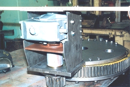
The company had a policy that its employees could buy scrap stuff out of the yard for scrap iron prices. The next weekend was spent tearing the boom off the truck and getting the bearing out.It weighed in at 175 lbs (79 kg). Was only 3" thick (7.6 cm), 32" (81 cm) in diameter, including the large bull gear teeth machined into the outer race to turn it around. Included also was a very large 23 to 1 worm drive gear box weighing in at 240 lbs (109 kg), that drove the bull gear/thrust bearing, and rotated the boom.The thrust bearing was in perfect shape.The worm drive shaft bearings were damaged from the impact, but could be replaced. The gear case was not cracked. I looked up the spec’s on the bull gear/thrust bearing and found it was rated for 25 tons! The gear box was rated at 18,000 ft/lbs 2446 m/kg) of torque with a 40 hp (cv) hydraulic drive motor. A side benefit of using this setup was that the worm drive reduction gear box also acted as a positive rotor brake, saving another design headache. With the worm drives torque rating there was no chance of damaging it in holding the antenna in position during very high winds. I paid the company $110 for 415 lbs (188 kg) of scrap. I rebuilt the gear box for $275. Another $17 went for a fifth of Wild Turkey to the mechanic who came up with the idea.(Surprising what a bottle of booze can do in these kinds of projects.) A new gear box would have cost $4,300. And a new bull gear/thrust bearing, $9,000. Unfortunately this was the last of the gifts from heaven. From then on the merchants in town always rubbed their hands together in wild anticipation when they would saw me come in. The drive motor For a azimuth drive motor for the rotor I had a very fine military surplus, weatherproof, 1/4 hp 115 VAC motor, geared down a 100 to 1, in a very compact gear reduction setup. I had this motor rewired to run in either direction. To the AZ motor output shaft I attached a 2 to 1 sprocket and chain drive. This then drove the input shaft on the worm drive reduction box for another 23 to 1 reduction. The output shaft pinion of the worm drive then drove the bull gear on the thrust bearing at a further reduction of 7 to 1. A total reduction of 230 to 1. The 1/4 hp motor had no problem turning the rotor in any condition. It also worked out accidentally to rotate the rotor at 1 rpm. Which worked perfectly for being fast enough to move the antenna around, but not so fast as to be to fast in movement to allow for fine adjustments. Cost of the modification : $45 for the motor rewire, $40 for the sprockets and chain. The motor had been gathering dust for 15 years waiting for a worthy project. To attach the bottom of bull gear/thrust bearing to the pole, and then attach the bull gear/thrust bearing to the upper part of the rotor, I had two, 1 inch thick (2.5 cm), 30 inch (76 cm) diameter steel disks flame cut out at the local steel supplier.
The thrust bearing had been attached to the truck bed with 16 high grade 5/8" bolts on either side of the bearing.Measuring out and drilling the holes for the bolts in the plates was no small project. Even when using the utility companies equipment that was made for doing such things after hours. Each plate weighed 170 lbs (77 kg). The center of both plates was bored out with a 4 inch hole for the cabling and wave guides to run up through the pole pipe and to the rotor system and antenna.(At the time I thought a 4 inch hole would be more than adequate. By the end of the project the holes were “just” big enough to squeeze everything through with sleeving to protect the cabling from chaffing on the plates as the rotor turned.) The lower plate attached to the support pole, so I also had to bore out 12 holes for the poles flange to bolt to the center of the plate, around the 4 inch hole that the cabling to passed through. I made all the bolt holes in the plates slightly oversize to allow for measurement errors, temperature changes, bolts not being exactly the same diameter, etc. This had an unexpected benefit that when these plates were being lowered by the crane onto the pole in a slight wind, and your trying to control and bolt up a swinging 170 lbs (77 kg) plate next to your head, it is nice when bolts slip in perfectly. On the upper plate I made a 1/4" thick steel box to not only protect the worm drive from the elements, but also to hold it to so it didn’t rotate from the worm gear torque. The problem was accented by the fact that Imight need to pull the gear drive someday for repair. So I couldn’t just weld up the entire box. Yet the box had to be strong enough to resist the tremendous torque and not be torn off. I got around the problem by first making all the sides of the box fit together very tightly. I left the back end open for access and oil addition. I spot welded 1 inch angle the entire length of the inside of each side plate, where it would bolt up to the end plate. This was done with the box end piece clamped in place to assure an accurate fit before spot welding the 1" angle iron on one side. Holes in the top and back plates of the torque box had already been drilled for hex head sheet metal screws. Next the holes in the angle iron were drilled using the holes in the end and top plates as a template and drill guide. The box was then bolted up to the gearbox mounts, the end and top of the box bolted up, and then the two sides of the box were welded to the upper 1" p. The reason for all this care was a 1/4" thick piece of plate was being welded to a large mass of 1" thick plate. Unless the box was all fitted together and rigid, the individual 1/4" side plates would have been totally warped out of shape from the heat of the weld bead as they expanded from the heat, while the heavy plate did almost nothing. If the welding of the unit had not been done in this way it probably would have been impossible to get the box sides to match again after welding and to bolt up accurately with the rest of the box. Last chapter
|