|
Don't
be afraid of CCD
|

|
|
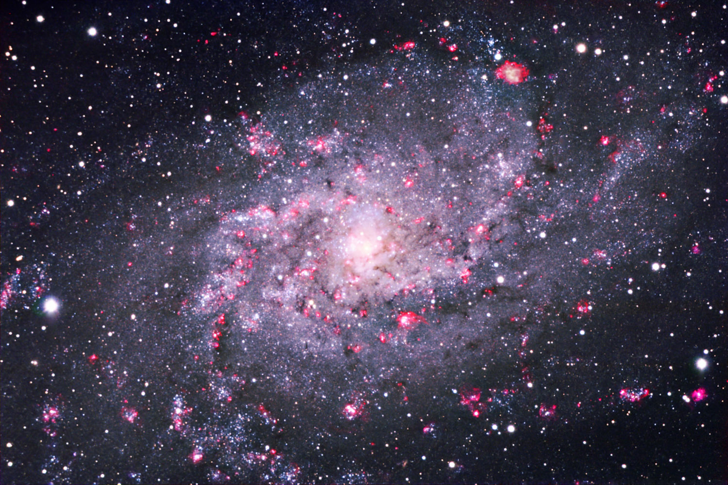
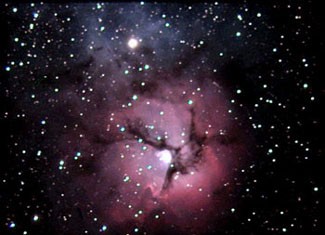
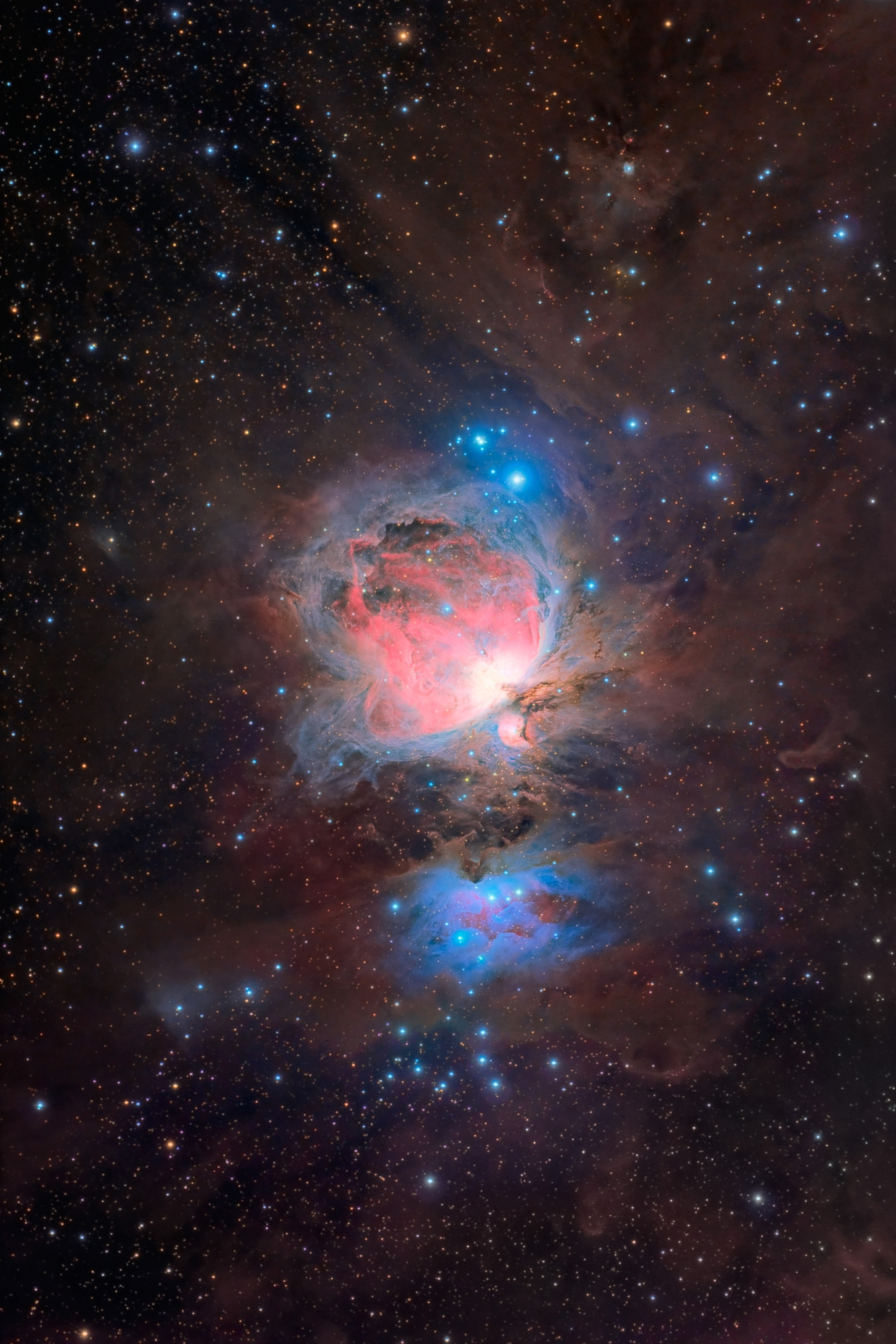
LRGB+Hα
image of M33 recorded by Jason Ware
with a Meade ACF 12 of 400 mm equipped with an Apogee U9 6303E CCD. Total
integration time of 520 min. |
Integration
time (IV)
The
integration time mainly concern deep sky astrophotography because in planetary
photography, except Pluto, asteroïds and comets, all celestial bodies
support snaphots.
The
typical integration time to record a deep sky object on a CCD is usually between
1 and 5 minutes operating the camera in 1x1 or better in 2x2 binning (merging two
pixels reduces the resolution of 50% but increases the CCD sensitivity). This way using a
100 mm f/6.3 scope we reach magnitude 18 in only 5 minutes of integration
and magnitude 20 using a C14 of 350 mm at f/6.3 !
In
the worst cases, the integration can last 30 minutes on prime focus of 400 mm scopes to record faintest galaxies (or faint spectra) and 18
times more if you want to produce tricolor composites !
Why 18 times ?
Because using a colored filter the incident light passing through the
filter is reduced and the CCD camera requests 6 times more exposure to get
the same result than an unfiltered image. Then you must take at least 3
exposures, in red, green and blue channels (some add a fourth channel, the
luminance with is a grayscale image).
Add to this constraint CCD
registration offsets, frame shifts that can occur with fast moving objects (Jupiter, etc).
Therefore color CCD is another challenge reserved to the experienced
amateur. This is however the best solution to records sky colors but at a
time and financial cost.
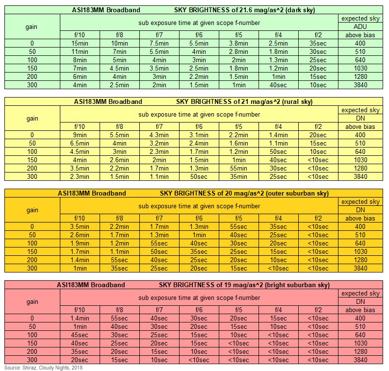
Below
are displayed two tables of integration time dedicated to B/W CCD, the left one for
the old but classic Kodak KAF-0400 CCD, the right one for the ZWO ASI183MM CCD in broadband mode (created by Shiraz).
|
KAF-
0400 specifications on a C8 f/6.3 scope
|
ASI183MM
integration time
|
|
S/N
ratio |
B/W
exposure |
Tricolor
exposure
through RGB filters
(2x2 binning) |
Noise level
for 30 stacked
1 minute exposures |
 |
|
Red
(585-680) |
Green
(496-585) |
Blue
(380-502) |
|
9 |
1 min |
2.2 min |
2.2 min |
10 min |
1.00 |
|
28 |
5 min |
12 min |
12 min |
80 min |
1.12 |
|
50 |
20 min |
41 min |
41 min |
5.5 hrs |
- |
|
Another solution is using a
"one shot" color CCD. Astrovid
Starlight Xpress MX5c among other models uses a color matrix filter over the pixels composed
of "secondary color" dyes in a grid of Cyan, Magenta, Yellow and Green
(like the popular CMYK technique). The filters are arranged in such a way that
the Luminance component of the image can be extracted with high definition.
Ideally
the light reduction is only 33%. The resulting color image is fine but at the
expense of lowering the resolution and longer exposures. Also, the MX5c is cooled,
but not regulated. That means that you need to take a dark frame at each ambient
temperature level each time you use it. Of course you can get this dark frame by image processing too.
Until
early 2000, Astrovid had few competitors among them HiSis, Lynxx, Meade
and SBIG. These systems didn't include automatic functions. Since
that time, the technology has quickly progressed. Not only CCDs are more
efficient and larger but they also include automatic functions :
auto-focusing, auto exposure settings (optimization), auto-stretch (to bring out
dim objects), automatic dark substraction (dark frames are stacked, averaged then
substracted automatically), auto-align and stack images, etc.
A
handful manufacturers also offer color cameras with a low form factor like
e.g. Atik 460EX, QHY12
or very small models like SBIG
ST-i Planet Cam and Autoguider, all very adapted to small installations
and planetary imaging.
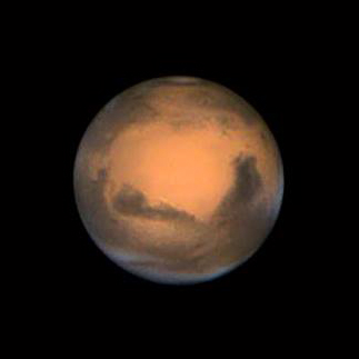
The
overall resolution of first color CCDs was lower than a monochrom model due to having
two arrays together. Although this physical limitation results were not bad at all,
with time and new chips, these small color CCD have much improved and give very good
resultats, specially in planetary imaging as confirms the above excellent image of Mars.
However,
for deep sky imaging, if you are really into critical observing then you have
to choice a monochrome CCD camera and acquire a color filters wheel with quality filters
(e.g. from Optec). This combination will allow
you to adjust the color channels (L,R,G,B, and Hα or CMY) integration times for
the sensitivity of your chip, do astrometry and photometry
works and even study any object using a single bandpass.
Common problems
Performances
of CCD cameras and their defaults go two of a kind and is it in vain
to expect recording good images if you do not control all factors that enter
in our equation. So let's describe clearly the problems that you can encounter
in using a CCD camera and methods to avoid them or to reduce their effects.
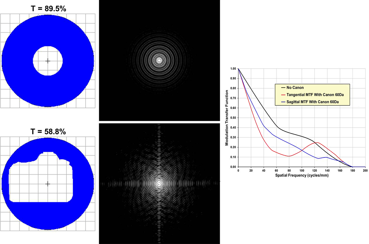
Form factor
It
is a technical term borrowed to physics qualifying the profile of a device
(linked to the flow amount reaching a surface). Using
a DSLR at the prime focus of a Schmidt-Cassegrain
scope, with its length of 12-14 cm, we immediately note that its position
just in front of the corrector plate creates an important obstruction,
specially in scopes below 300 mm of aperture.
As
we see in the below left graph, a Canon EOS 60D DSLR fixed at the prime
focus of a C8 system affects seriously the Airy disc of a star, and
we lost up to 25% of the image details compared to a system without DSLR.
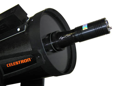
To
read : What are Fastar and HyperStar? How do they
work?, Celestron
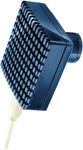
To
resolve this issue, the user has to purchase a low form factor DSLR
(e.g. Olympus) or a small cylindrical CCD (Atik 460EX, Nightscape 8300,
etc.) that he will mount on a Hyperstar
system from Starizona as we see above (or on the old Celestron Fastar optical system
but discontinued since 2005).
In
the event (rare) of this solution should be too insecure or unstable on
small and light installations, the alternative is using a small HD webcam. Otherwise
there is no other choice that either using the Cassegrain focus with a focal
reducer (but the weight will be similar) or better, using a larger scope
in order to reduce the relative obstruction generated by the sensor placed
a the prime focus.
Focusing
Focusing problems and fine focus
adjustments are emphasized using electronic camera with a telescope. Since the CCD
field is very small, especially in planetary imaging where we works with an
eyepiece projection (or a Barlow), a special attention must be given to stabilize
image shift and temperature changes. Typically a shift is equal to the square of
the amplifying factor of the secondary mirror, which is 5x on a f/10 SCT. A mirror
shift of only 0.001 mm creates a focus shift of 0.025 mm which is easily recorded
by the CCD detector.
To
read : Practical formulae
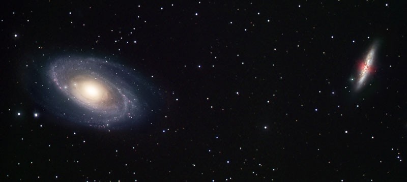
 |
|
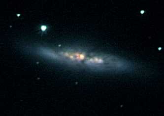
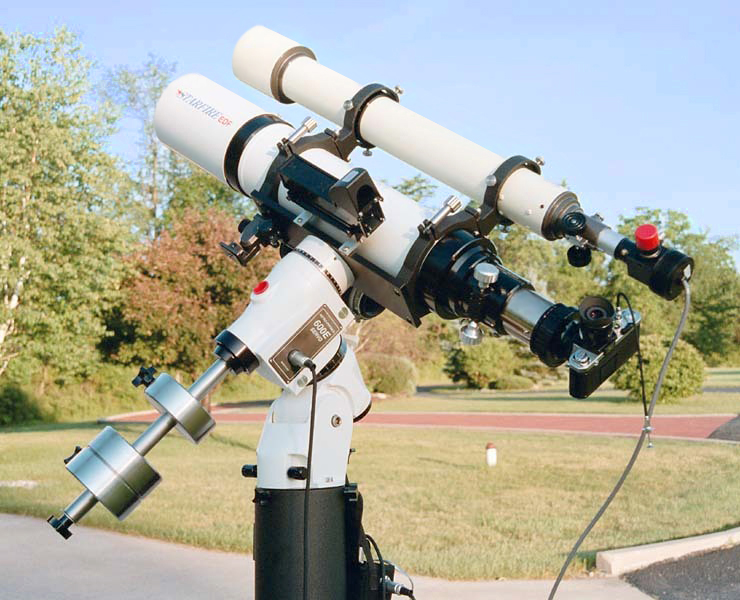
RGB image of M81 and M82 recorded by Robert
Gendler with a 12" f/9 Ritchey-Chrétien scope fixed on AP1200
GEM equipped with a SBIG CCD camera. |
|
Then the focal point
positionning varies roughly as the square of the f/ratio. So using a scope at
f/6.3 requires a focusing 2.3 times more accurate than at f/10. At prime focus
of a f/6 scope, the depth of field (or focus) is only 0.0127 mm or 0.005".
Therefore a zero-shift electrical focuser is highly recommended (like the JMI NGS-F
or Robofocus for SCT's) as a locking mechanism
to tighten the all imaging train when heavy accessories are attached.
So prior taking your
first CCD pictures of celestial bodies, a short calculation will be useful to check the
accuracy of your CCD camera in combination with your optical system.
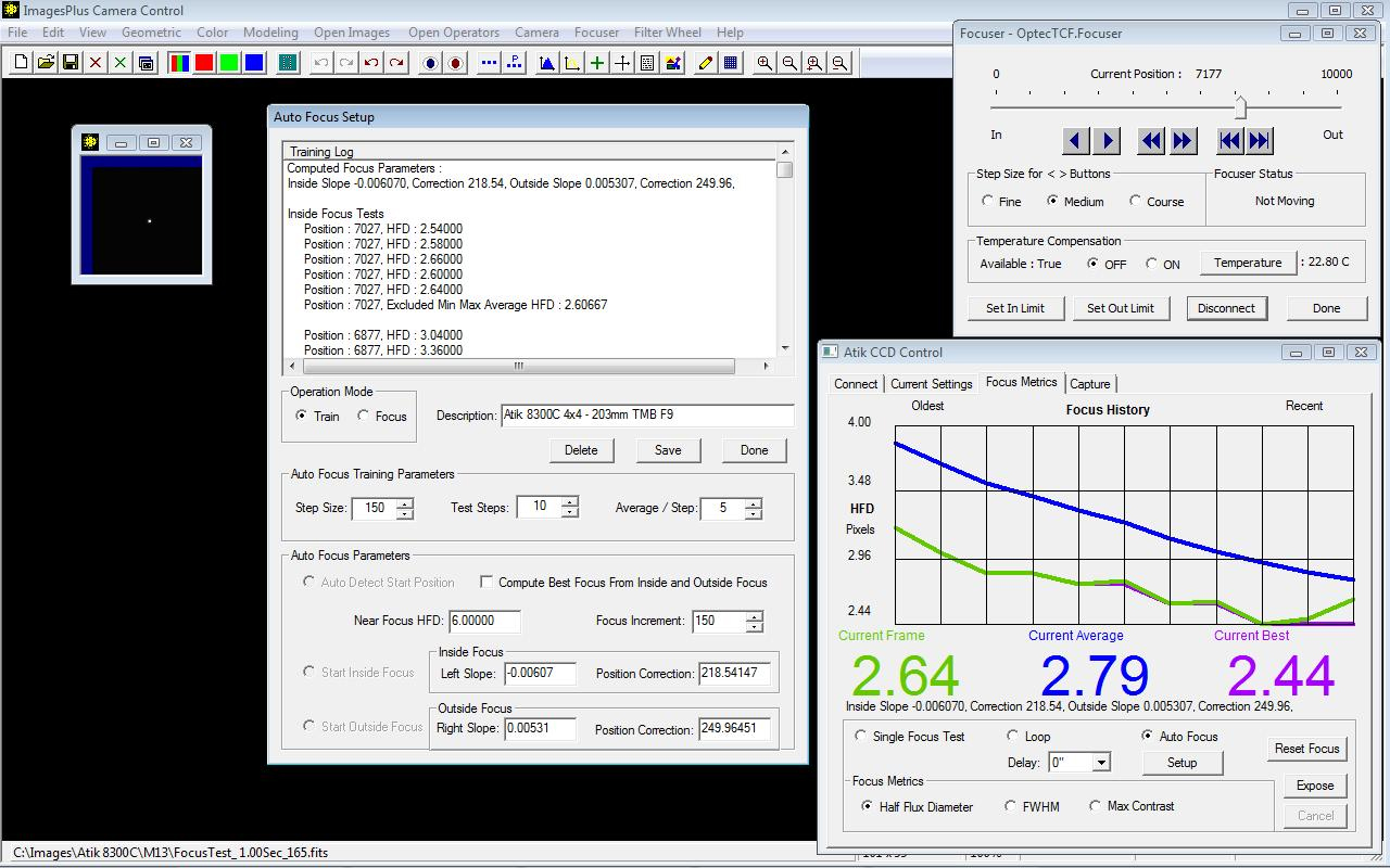
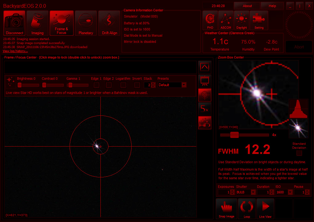
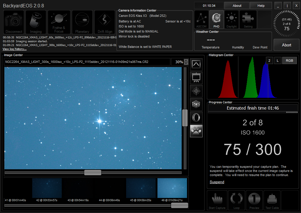
The
software provided with most CCD cameras includes a menu dedicated to
focusing that takes in charge the tedious task of finding the focal point
on the CCD sensor. The camera takes a serie of shoots of a preselected
area in changing slightly the focusing. These images are usually exposed
about 1 s for bright objects and 10 s for the dimmer. Then the system let
you select the the most sharp image. Some models let you also take
immediately a dark frame (see further) before the light or raw image. Once the focus is
achieved, remains to center the object, either in low resolution to
increase de sensitivity or in full mode.
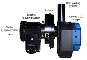
Optical
train and backfocus
As
in the time of the argentic photography, near the focal plane some optical trains can be
quite long and heavy up to create a problem of backfocus or to put the
stability of small installations at risk. Indeed, a complete imaging train
can include : an electric focuser + a focal reducer + a field rotator + an off-axis
guider + an adaptive optics + a filter wheel + a CCD camera. Its total length
is 20-40 cm depending on whether the accessories are thin or large.
Hopefully there are solutions
to shorter the length of this set as for example to place some accessories elsewhere (the external
electric focuser in the focuser knob of SCT or in the Crayford, the focal reducer in the
SCT visual back, etc.) and replacing the off-axis guider and the CCD with a dual-chip CCD
combining the auto guider and the imager and including a filter wheel. At
the end, it remains an adapter, the field rotator, the adaptive optics and a (larger) CCD camera. Depending on
accessories, we can reduce the backfocus between 5 and 20 cm or up to 50%
of its length.
To
read : How to Set the Correct Back Focus for Your Telescope (Guide),
OptCorp, 2021
 |
 |
|
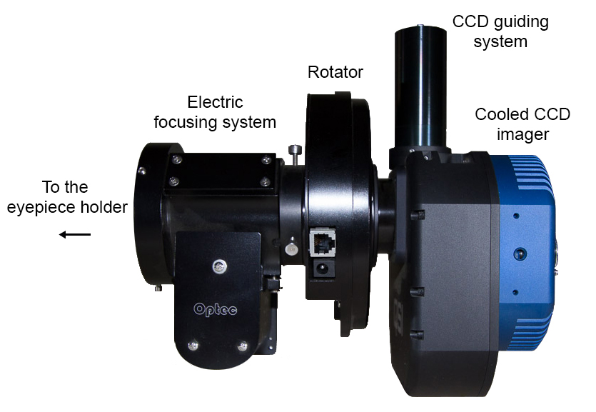
At
left, a typical optical train (CCDs are a QSI 683wsg-8 imager including a guide port
in which is inserted a Lodestar guide CCD. At right, the use of accessories at the ocular
side request to insert a spacer to reach the focal point on the photosensor.
Documents manufacturer and OPTCorp
adapted by the author.
|
|
Thermal noise
What
ever the camera used, the CCD or CMOS sensor being usualy not cooled,
astronomy images recorded in low light conditions appear grainy, all the more
at summer when the outside temperature increase the thermal noise.
In
an ideal CCD camera, each pixel would give a brightness level of 0 when
there is no light, and a value increasing perfectly linearly with
increasing light until it became saturated. In addition, the reponse of
every pixel would be identical. Actual CCD cameras are far to reach this
ideal objective.
 |
 |

|
|
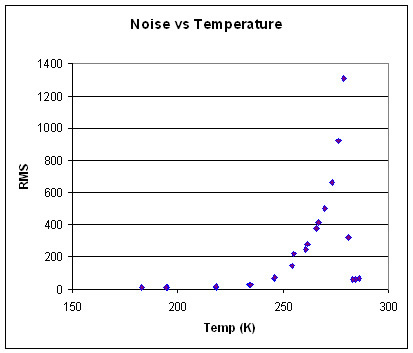
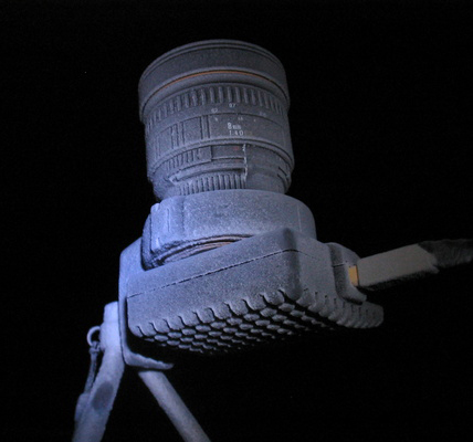
At
left, the increase of thermal noise with temperature of a
CCD. At center, a Meade
DSI CCD camera equipped with a Sigma 8 mm lens covered
with ice but till working by -70°C at Concordia base in
Antarctica. Document G.Dargaud.
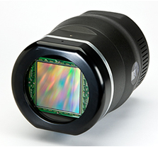
At right, a Spectral
Instruments CCD 1300S (100 kpixels of 9 µm)
cooled to -100°C. |
|
The
first reason is that the electron count for a pixel is a function of the
number of photons that strike it plus the number of electrons due to
"thermal noise" or dark current. In using electronic components, for lack of an
ideal efficiency (100% of the inpout energy should be converted without
loss), they dissipate some heat that generates a thermal noise that is
reduced by half for every 6 or 7°C decrease in temperature. This
reduction in the total dark current generation rate has of course
limits; most CCDs do not function well below -120°C. As shows the below
graph, in pratice the dark current is almost removed around -100°C
where the image only shows random read noise.
Like
with photoamplifiers, a CCD sensor is thus very sensitive to infrared,
ambiant temperature and temperature changes. For years many amateur
sensors are cooled and the best are regulated with a stability better than
0.5°C. This cooling can be reached in isolating thermally the device from
its environment. High-ends CCDs are commonly cooled with liquid nitrogen
like the PixCellent
system that can reach -120°C but the treatement is expensive. The
alternative is the thermoelectric
cooling that by Peltier effect allows CCD cameras and some high-end
DSLRs (e.g. Canon ESO 600D and 5D equipped with a CMOS sensor) to
reach -35 to -40°C below the ambient temperature depending on
models, and exceptionnally some Spectral Instruments
models are cooled to -100°C. At last, cheaper, one can also use a cryo-cooler
with a mechanical pump.
 |
 |
|
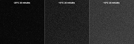
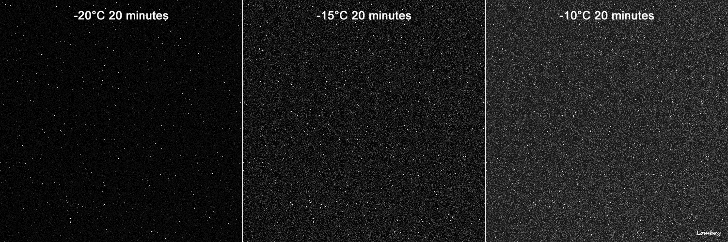
Effect
of cooling on electronic noise of CCD and CMOS sensors. At left,
"dark" frames of a SBIG STL-11000 CCD cooled
respectively at -20, -15 and -10°C. At right, "dark"
frames of a Canon EOS 600D cooled at -9°C and at ambient
temperature of 25°C. All dots are in fact parasits created by the
electronic device ! Each time that the temperature drops of 5° the
thermal noise is reduced by half. These images are the perfect illustration. |
|
Note
that external infrared sources can potentially
be seen by the sensor although invisible to your eyes. So remove all bright accessories
in the neighbor of the sensor which emit infrared light or are not black anodize
(or painted flat-black) which is also a good infrared absorber. Such sources are
eyepieces holders, digital clocks, digital circles, dew heaters... So, to
avoid any parasitic noise, it is advisable to place the CCD camera at ambient
temperature and to wait for about half an hour after to have
switched on to take your first pictures.
If
your images show a thermal noise even using a cooled CCD camera, you can
till reduce this noise and increase the signal/noise ratio thanks to an
image processing in two steps, pre and post processing. procedures that we
will describe next page.
To
read : Input-referreds
Read Noise vs. ISO Setting, Photons to Photos
Digital Camera Reviews and Sensor Performance Summary,
ClarckVision, 2016
Readout
noise
|

|
|
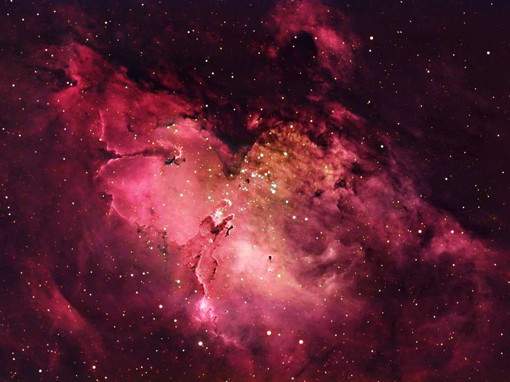
M16
in Serpens. This is a composite of three RGB images recorded with
three Astro-Physics scopes : a 180 mm f/7 EDF refractor, a
Maksutov-Newton 235 mm f/4.3, and a Maksutov-Cassegrain 250 mm
f/14.6. These scopes were equipped with CCDs
SBIG ST-8 and ST-10 with a CFW-8 Color Filter Wheel, FLI MaxCam
CM10-2E with a Custom Scientific Hydrogen Alpha Filter. Images
were processed with CCDSoft, Mira Pro, Maxim DL/CCD, Sigma
Beta, and Photoshop. Document published with the courtesy of Philip
Perkins, Trent
Kjell, and Roland
Christen. |
This
degradation is caused by statistical errors in reading out the number of
electrons per pixel (photosite). This relative sampling error decreases
inversely with the square root of a pixel brightness level (DN factor).
Then the final problem is that the pixels are not equal in their light
sensitivity, with typical variations of 1-2 percent among the photosites
in an array.
Resolution
and binning mode
Deep
sky imagery with a CCD camera requires preferably larger pixel dimensions
because large pixels simply collect more photons than smaller. This is
what we call the binning, a mode that offers the possibility to sum signals
from several adjacents columns and rows of pixels (binning 1x1, 2x2, 4x4,
etc.). But, drawback, in binning mode 2x2 the resolution drops
of 50%, but the sensitivity is improved.
Conversely, in lunar and planetary
imaging the amateur searches for the higher resolution and does not need so much
light sensitivity. In this case a smaller binning mode is preferable. At
last, there is a tendency toward CCD cameras using larger array sizes.
A 16-bit "depth" (65536 brightness levels) is preferable to 12 bits (4096
brightness levels).
But all these aspects affect the size of the image,
the download time and processing as well as the disk space need to save
this file. As for the color, this is no more with 12 or 16
bits that we work, but at least 24 bits. In this case the file size is practically
no more managable by amateurs standards and users of scanners know very well that
problem. This is for this reason and for an image quality question too
that the usage wants that amateurs work from LRGB images to get color
composites instead of using color cameras.
Accuracy
of the driving system
To picture
deep sky objects, the last mechanical element that could potentially be a source
of problems is the motorized mount. As explained previously, using such an accurate
device as a CCD camera, you dramatize the stability of the instrument and it is mandatory
to use a sturdy mount. Have always in mind that the mount is more important than your
optics; you will get easier fine pictures with an ordinary optics fixed on an excellent
mount than the contrary.
From
a pure photographical aspect, an Alt-Az mounting will display the problem of field rotation while you
will track an object across the sky. Field derotators made for the popular SCT's are
just adding one more mechanism and a new freedom axis to drive. The Alt-Az
mounting can only be use for Lunar and planetary imaging since the exposure time
are short (faster than 1/10th sec or so).
For
all pictures of DSO's in high resolution the equatorial mount is mandatory (or
an altazimutal set in equatorial mode). There is only one exception; scopes of
250 mm and larger can use an
altazimutal mount but have to use a derotater to avoid stars trails in the
corner of the image. This heavy and cumbersome accessory is not recommanded for
smaller scopes.
The
mount must be well polar aligned and driven by an accurate system which errors
are limited to a pixel. Any larger guiding irregularity will be
recorded in the image. Therefore many amateurs get support from an auto-guide
CCD. But the accuracy of a german mount equipped with classic gear wheels and
a Periodic Error Correction system (PEC) is about 1" while a Direct drive
mount (see this French page) driven by an
electromagnetic field goes below the diffraction limit, reason for which many amateurs have
adopted this kind of mount. The image gallery is eloquant in this regard.
AutoGuider
Calculator, CCDWare
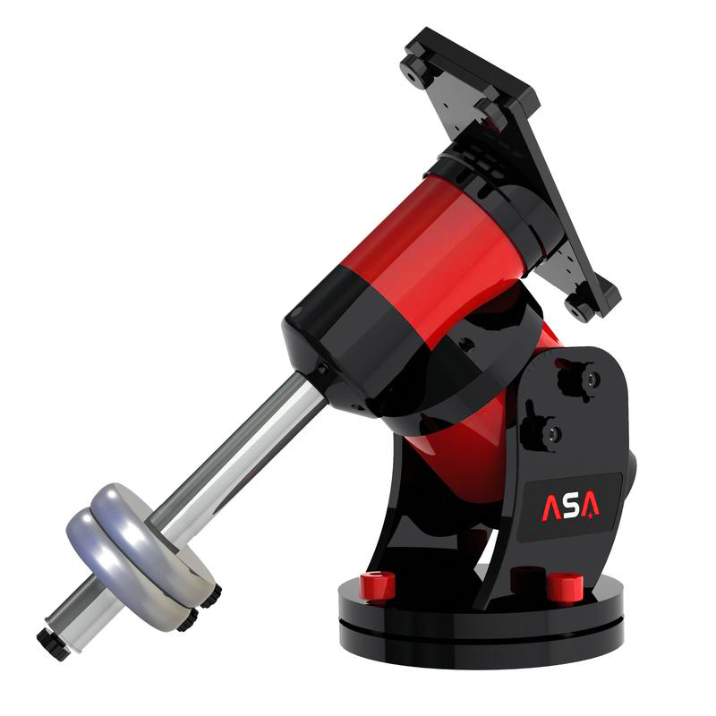
Several
manufacturers provide Direct drive systems to name Alcor System
(France), ASA (Autria), Astelco
(Germany), GTD
(USA), PlaneWave (USA), SkyVision
(France), etc. Note that Alcor System and SkyVision work in
partnership with Optique Unterlinden
(France).
When
all technical (and financial) issues will be solved (advice of a qualified
vendor or experimented amateurs is not useless) you will be ready to picture
your favorite celestial object. The good news is that after looking at some CCD
images produced by amateurs and their equivalent taken by professionals,
subtle is the one that can say who is on first and who is on second!
Of course, getting closer, the bigger always wins, but do not forget that
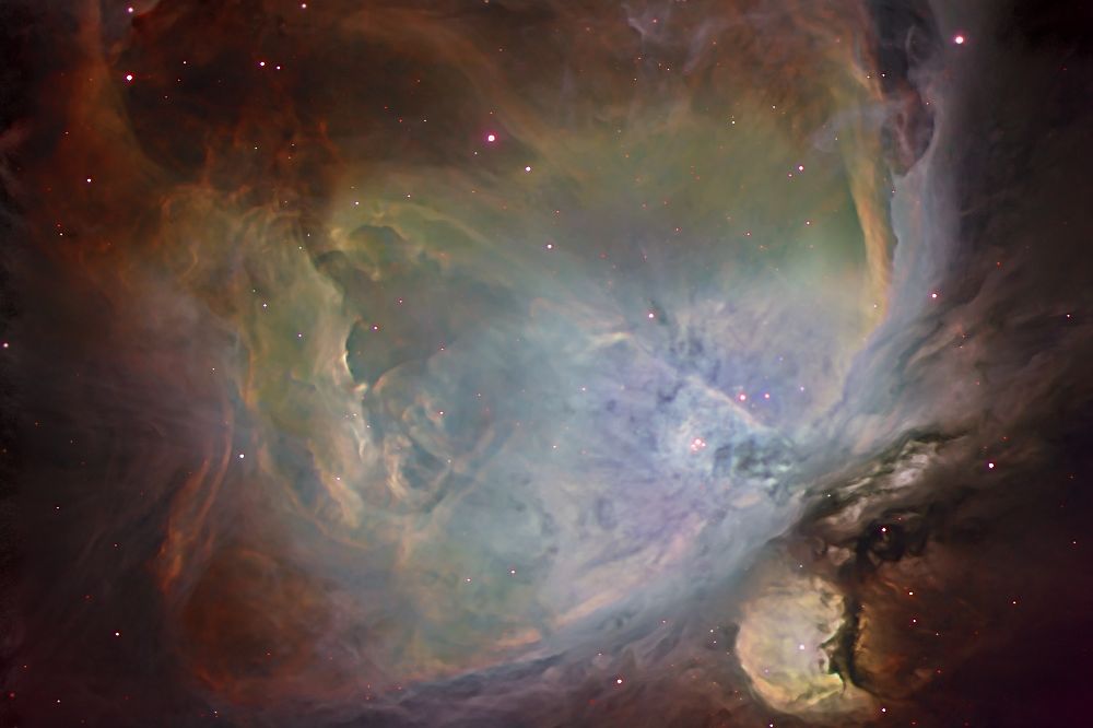
image processing can cover one's tracks... Let's compare for example M42
pictured with the HST
and by Jason
Ware using a RCX400 of 305 mm f/8 or Officine
Stellare with a Riccardi-Honders RH of 200 mm f/3... In one
generation, technology available to talented amateurs has done a giant leap !...
Now
that we recorded our pictures of the celestial objects, some additional
frames need to be recorded before processing our raw images on computer.
This step is called the calibration or pre-processing. It is the subject
of the next chapter.
Next chapter
The
calibration or image pre-processing
|


