Technical
review
|
|
|
Polarization
of the cathode |
Gain
and transconductance (II)
At
first sight, the amplification factor defines alone the tube
performance. This is not true because the load resistance influences
much the amplification factor of the circuit. The more high is the
resistance, the more gain offers the circuit, what reduces the value
of that resistance, and the gain drops.
The
gain as it was defined earlier must be considered as a circuit
characteristic rather that the one of the tube, and this is for that
reason that electronicians introduced the transconductance (existing in
FET transistors too).
The
transconductance is defined as the ratio between the variations of
anodic current and the variations of the grid voltage. It is
expressed in mho or Siemens.
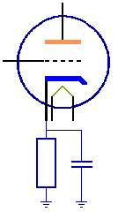
Polarization
of the
cathode
Instead
of using a battery to polarize the grid, power amplifiers working
with triodes usually take advantage of another system : the cathode
polarization, a solution much more flexible and simpler to set for
manufacturers.
In
the first circuit involving a triode, we used a battery that
we connected to the grid to give it a polarization voltage
and we placed the cathode to the ground because of the
negative value of its voltage. We were forced to make this
circuit because the cathode voltage (potential) was higher
to the one of the grid.
Manufacturers
proceed in another way, much less intuitive but more efficient. They
place the grid to the ground in inserting a small resistance in the
cathode. When there is current in the tube, a voltage drop will
occurs in the cathode resistance. Its potential will be higher than
the one at ground. In other words the cathode is positive in
relation to the grid and thus the grid voltage is well negative in
relation to the cathode.
Like
in most electronic circuits, the condensor is mandatory
because we are working with alternative current. Indeed,
current variations could produce voltage variations and thus
a variable polarization. This condenser suppresses all
voltage variations in derivating its alternative component
to the ground.
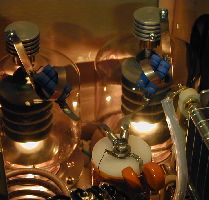
Vacuum
tube manufacturers are mainly represented in the U.S. and
are seen today as a reminiscence of the past, with the
exception of the special purpose types used in broadcast and
image sensing and displays. Today Eimac, GE, RCA, and the like are continuing to
provide several series of tubes, but in a rate much slower than in
the past, their main activity being concentrated to the production
of audio or transmitting amplifier tubes and beam power tetrodes.
Their competitors are the Russian manufacturers but which tubes
quality is not always on top. When the product is of quality (i.e.
3-500Z triode sold by RFParts)
the amateur can do a substantial saving vs their US couterpart,
which can be up to 10 times more expensive !
|
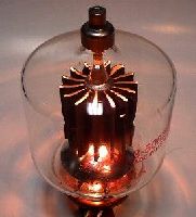
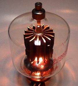
That
the light be : use your tube as a bulb ! |
|
At
right, two 3-500ZG in full activity in their socket in a
QRO HF-2000 amplifier showing a light glare in the
dark. Below, a 3-500Z triode outside its socket,
usually installed in a Kenwood TL-922. To
light it its filament has been powered under 5V at
14.7A. No need of high voltage. How to get
this energy ? If you own a 230V/6V at 75VA transformer,
add a 100W
resistance in serie with the 230V primary to get 5V on
the filament. The resistance will dissipate 15W.
|
|
|
You can also use a 12V lead or gel battery with a coil resistance
of 0.47W
able to dissipate 100W. At last the best solution is
using a stabilized power supply providing 5V at 15A.
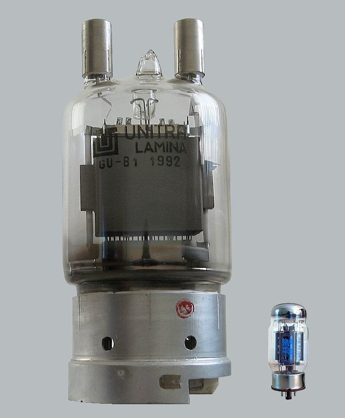
If you want to see a huge pentode tube GU-81
light, you must connect the filament pins 1 and 2 to a 12.6V at
11A power supply. Remember that when you connect the
voltage to your tube, the filament current will be
above 10A. Be careful and don't exceed the nominal
filament voltage ! |
|
After
have reviewed vacuum tubes and how they work, it is time to explore
their main function in HF amplifiers, I mean the signal or power
amplification.
Characteristic
curves
of a transistor
Although
vacuum tubes were promised to a bright future, in 1947 at
Bell Laboratories, Bardeen, Brattain and Shockley built the
first transistor
which, like a vacuum tube, was able to amplify signals.
The
transistor is an active electronic component constituted of
two PN junctions (in fact there are diodes made of a
sandwitch of P material and N material constituing
respectively the anode and the cathode) placed side by side
to form a NPN component.
In
the early 1950's, the tiny but very efficient transistors
began to replace the big and less reliable vacuum tubes in
radios and other electronic equipment. For decades
transistors have been used to swith currents or voltages, to
amplify, convey frequencies, mix them, among thousands other
things.
From
1960 it replaced amplifier vacuum tubes when IBM introduced its
first IBM 1401 computer. To understand how work a 1 kW amplifier,
there is nothing simpler than a transistor to understand is
functioning.
A
transistor works like a switch : saturated it let the current
through and closed it blocks it. We can also use it in an
intermediate state where it works like an amplifier. Let's explain
this principle.
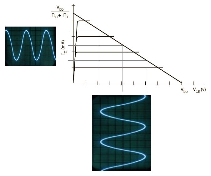
If
we trace the characteristic curves of a transistor on an
oscilloscope we get the graph displayed at left. On the load line
traced in blue three points are highlighted: the point of
saturation, the operation point or quiescent point and the point were
the load is blocked.
The
operation point is variable. If we
modify the transitor polarity (in other words if we change
the contineous voltage applied on it) it will move along the load
line between Vc=0 and Vce=Vcc. Between these
extrema, the collector current varies contineously,
producing a drop of voltage in the collector resistance.
This drop of voltage follows the current variation according
U=RI. The voltage U=0 when the transistor is blocking (below
at right), then increases along the load line to reach U
when the transistor is quasi saturated (above at left).
Our objective is
to use this transistor between both
extrema, in a way to avoid blocking and saturation, thus in
a narrower band along the load line.
The
pattern of this voltage fit exactly the current one that we
want to use in our amplifier, excepting that in practice our
external polarisation elements are fixed and we cannot move the
operation point. So how can we move it along the load line ?
The
only variable in your system is the input voltage that we
need to amplify and that we can apply on the base of our
transistor.
The
signal being alternative, positives alternations will be
added to the actual polarisation voltage what will increase
the polarisation of the Base-Emitter junction. This effect
wil increase the current in the Base (Ib), thus in the
collector (Ic). In a similar but
inverted way, negatives alternations will be substracted
from the actual polarisation, reducing the current in the
Base, thus in the Collector too.
As
we can see on the drawing at left, in the upper left part
of the graph a small alternative voltage is applied at the
entry. This variation is find amplified below at right in
the form of voltage between the transistor Collector and
Emitter.
But
we need to route amplified alternative signals to the Base
and recover them on the Collector. How to proceed ?
Only
one component is able to let through alternative signals and to stop
the continous one : the condenser. Its second characteristic
is to display a reactance (resistivity) depending of its capacity and working
frequency. So we will need a specific condenser showing the smallest
reactance, acting like a circuit-breaker for alternative signals.
These condensors are named coupling condensers.
When
we create an amplifier, we send signals to amplify to the Base of
our transistor and we "load" the emittor diode. We can
then calculate the direct resistivity of this diode. Long
computations allow us to define that the resistivity (Re) of a
emittor diode in AC is equal to 25mV/ Ie. This approximation will
allow us to estimate easily the amplification gain.
Next
chapter
Amplification
classes

