|
Technical
review
How
to select a tube HF amplifier ? (II)
Capacitors
Knowing
that the voltage can exceed four times the DC plate voltage,
manufacturers use large "door-knobs" capacitors suited to
handle high RF currents and should no more use ceramic disk
capacitors. Usually we find 2 or 4 door-knobs capacitors
working in parallel. When using several capacitors, each of them
yield a low capacitance in order to carry higher current that a single
capacitor of higher value. These capacitors are then connected in
series with the plate tank capacitors to slow down the tuning rate
of the plate tuning capacitor.
 |
 |
|
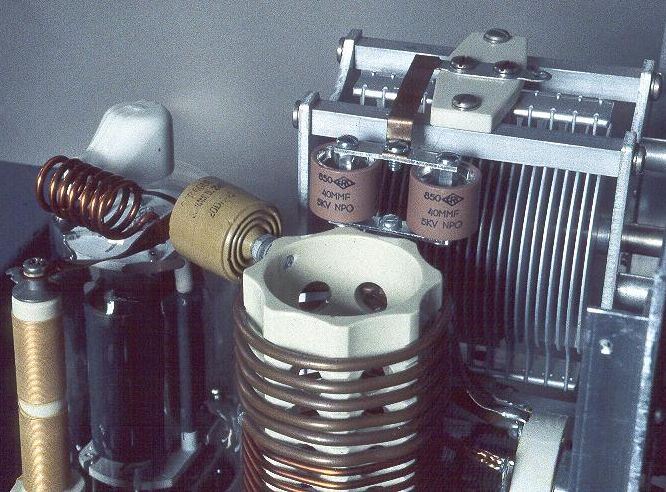
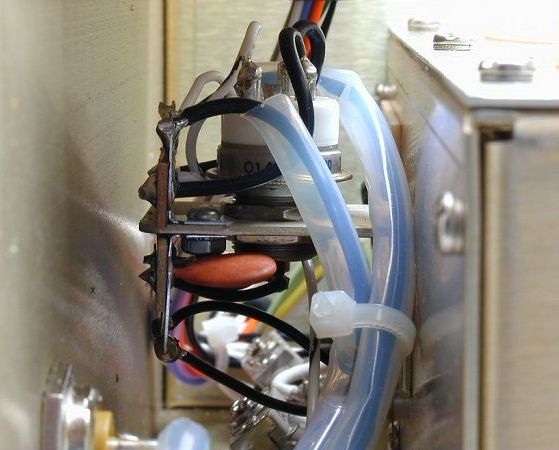
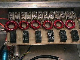
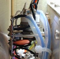
Closeup
inside the Wingfoot
813 amplifier. At
left in dark red is the parasitic surpressor that
prevents undesired oscillations in the amplifier. Just
to its right is the yellow plate coupling capacitor,
which keeps the 2 kV plate potential from reaching the
plate tank circuit located just in front of it. Above
the plate tank coil are two 40 mf
"door knob" capacitors. Their function is to
control the tuning rate of the plate tuning
capacitor. In the image at right the antenna RF choke is
the small device standing in the front and at right. |
|
Antenna
RF choke
Located
between the output antenna connector and the ground it serves two
purposes. First it should ground the plate loading capacitor for DC
so that the loading capacitor handles only the output RF. Then it
should short circuits the plate supply in the event of a short in
the plate coupling capacitor. This will blow the security fuse and
prevent the 2 kV plate potential from reaching the antenna
system. How ? A leaky coupling capacitor lets current through from
the preceeding stage and upsets the DC bias, usually turning the
tube in such an hard way that no signal can pass through it. A power
tube with a leaky or shorted coupling capacitor may blow fuses and
cause low power or even damage transformers.
Pi-L
network
The
Pi-network is a symmetrical circuit that tunes the
output tank circuit and transforms the load resistance in the
nominal 50-ohm load. This is an excellent harmonic attenuator.
To avoid harmonic distortions, the old Pi-network is usually replaced
or complete with a Pi-L output network. Knowing that the quality
factor Q measures losses (from conductor and dielectric) in a
resonance circuit - the sharper the tuning curve, the higher the Q
-, this factor defines its selectivity and sensitivity (Q =
frequency / bandwidth). Applied to a Pi-L network a Q-factor 12 is enough to avoid any
distortion.
 |
|
|
At
left, a Pi-L network schematic. At right, an input
circuit made by SM2CEW constitued of one tuned circuit
per band. |
|
T-network
attenuator
Also
named PAD attenuator, this is a tuned network made of variable
capacitors forming the arms of a " P"
and two parallel inductors forming the top (also designed as a
"T" network, hence its name). Its role is to attenuate or
suppress harmonic distortions to present a 50-ohm load to the
exciter and then to the tube, the tuning offering the advantage to
get the lowest SWR and loss as possible.
To
work on all bands, including WARC, it is recommended of using individual tuned input
T- networks for each band. This design will increase the Q factor
and thus is far best than trying to use a single tuned network on several bands.
Direct feed of the tube is
not recommended even if at first sight a tube supporting a 50-ohm
input impedance could be directly fed by the exciter. In fact this
nominal load is well present but only during half a wave of the input
cycle, whilst during the other half of the cycle, the
impedance load can yield any value. This effect distorts the input
signal, increases losses and SWR during that time.
Instead
of using a T-network we can also take advantage of a passive
resistive input network. It can be found in many high gain triodes
and larger multi-grids tubes, including pentodes.
Variable
capacitors
To
adjust a radio on a frequency we use variable capacitors which role
is to equalize the inductive (from the inductor coil of the
transformer) and capacitive (induced by the counter electromotive
forces) reactance; this condition is called resonance. The
particular frequency isolated by the equalized reactance is called
the resonant frequency.
To
tune an amplifier on the same resonant frequency as the radio we
can use variable capacitors or switched fixed capacitors also called
loading capacitors. The first are the most commonly used. They come
in butterfly or differential model. Among usual problems, some unstable
amplifiers or if you work on unappropriated high bands (i.e. on 10m
where the capacitance can be too high) can lead to arcing the
loading capacitors due to an extensive use. This problem will create
paths of low resistance and in this case it is recommended to
replace the plate. Therefore before buying an amplifier verify well
its working frequencies to avoid such mistakes.
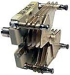
Butterfly
capacitors support high voltage up to 5 kV, with plate spacing
as small as .030" (0.8 mm). Quality floating stators and rotors
should use silver plates and 1/4" shaft. Do not use a split
stator as it yield a higher loss.
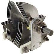
Differential
capacitors plates should be tapered for
uniform capacity distribution during rotation. Complementary tapers
increase capacity in one section while decreasing in other. Rotor is
usually grounded at shaft end and has a brush at rear.
Input-SWR
SWR-meters
display various accuracies, some are digitals others analogs, and
even using the same circuit different models of SWR-meters will give different readings.
Changing the length of the coaxial can also
change the SWR reading.
Modern transistor-output transceivers always use a set of switched
broadband output-filters, offering about 1.5-octave per filter, in
respect to the national regulation requirements on
spectral purity.
When
using such a filter at the limit of its bandpass, i.e.at 29.500 MHz, the filter can introduce a reactance into the transmission
line. This reactance might avoid any optimization of the SWR in the
amplifier tuned input circuits.
The best way to avoid this problem is
still using a tube-radio (e.g. Kenwood TS-830S) when optimizing the tuned-input circuits.
The radio must be first tuned for maximum power into a 50-ohm termination, and then
it must not be corrected during the adjustment of the tuned-input circuits. Indeed, if the
transmitter is tuned again, it may introduce a reactance that will
affect the SWR.
Band-switcher
Of
course in purchasing or building a multi-band amplifier, a quality band-switcher
is a must. Here also due to the high current, avoid the low cost
phenolic/bakelite switch and select a switch made of ceramic.
Similar to the electro switch, this last is up to 20 times more
expensive than phenolic, but it is much more resistant and sometimes
explosion proof, confirming its high efficiency.
Knowing
that a kW amplifier displays a peak voltage of about 10 kV DC, the band-switch should be able to carry
at least 20 amperes DC, the contineous component rating 60% of the DC
level. If you select a smaller switch the lesser failure of this
device will switch-off your amp immediately and in all cases you
will have to replace it. So the biggest the best and never skimp on
its quality.
At
last each year contacts of the band-switcher should be clean using a
dedicated cleaner to ensure it a top condition.
 |
 |
|
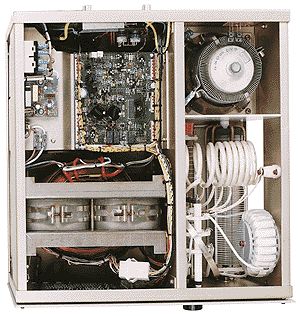
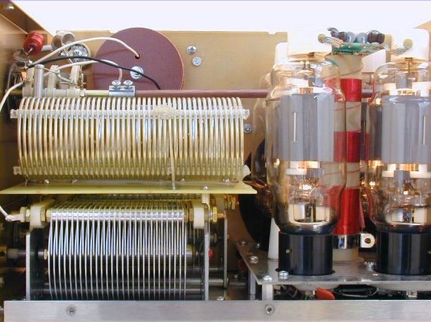
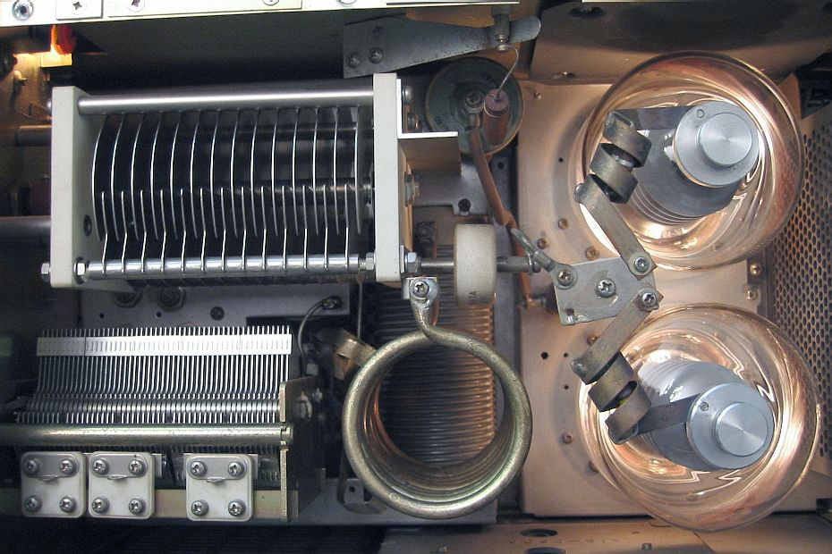
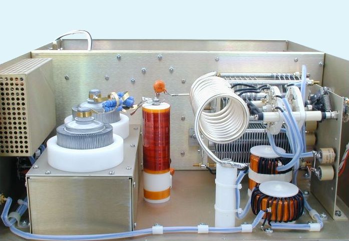
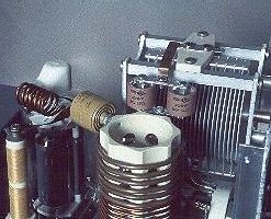
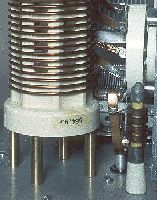
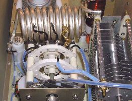
At
left, inside this QRO HF-2500DX
amplifier we recognize in the middle near the Svetlana 4CX800A/GU74B
metal/ceramic tubes, the orange plate choke on which are grounded blue
parasitic suppressors. To its right is the white tank
coil with the gray variable capacitors in the
bakground. Far right is the band-switcher
fixed to the chassis. At right, a closeup of the QRO
HF-2500DX Mark III RF tank showing the
band-switcher at foreground. An excellent quality ! |
|
Plate
choke
After
tubes and the tank coil, this is the largest component. This is a
cylinder displaying a diameter over 25 mm, 150 mm high and that
yield no less than 200 µH. The wire forming this choke is between
18-26 ga (0.4-1 mm) in size and insulated.
It
must be placed away from the heat radiated by the tubes to avoid
that it burns up. Therefore used with glowing
glass tubes (vaccum tubes containing gaz) chokes of small diameter
request to be placed in contact with the direct air stream coming
out of the blower. This problem does not occurs with metal/ceramic tubes.
The plate choke is usually not placed in a direct air stream but to
avoid overheat the plate choke displays a larger diameter.
Most
amplifiers working on all bands including WARC. To prevent parasitic
resonances on WARC bands a capacitors set named parasitic
suppressors is grounded in the plate choke.
However, before using it on WARC bands verify with the manufacturers
that the plate choke is modified consequently, otherwise you risk
to blow up the plate choke at the first emission.
T/R
switching
|
|
|
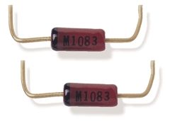
A
PIN diode. |
In
many amplifiers, the T/R (Transmit/Receive) switch is an open
frame mechanical relay (20 A). Although reliable, even after 20 years or
more of use, this kind of switch is loud by design and can not
switch fast enough to allow amateurs to operate fast break-in (QSK)
in modes like CW, SSB-VOX or AMTOR. Indeed in these applications is
it requested that the switching reaches or is below 3 ms. To get
this speed some modern amplifiers can be equipped at extra cost with
vacuum
relays or use from factory high
power PIN diodes. A
vacuum relay is sensible to failure when used in high RF
applications and is a bit louder than a PIN diode. This
latter on the contrary is an active semiconductor that operates as a
variable resistance at RF and microwave frequences.
The PIN diode resistance is
determined by the forward biased DC current. Better, in switch
applications the PIN diode is able to control the RF signal without
introducing distortion.
PIN diodes
should be your best T/R switches because they are much quieter and faster than
vacuum relays.Drawbacks, PIN diodes
must be associated to a complex circuit constitued of dozen
components; they are subject to damage by electrostatic discharges
(i.e. lightning), and when SWR is high,they don't have
a great reliability record and tend to fail due to high RF voltages and currents.
Of course they are not the sole components to fail in such
conditions.
Two
worlds dealers are recommended, Jennings
and Kilovac.
Both manufacturers provide high-speed relays (3 ms) rated up to 30 kV
peak and that handle over 30 A if necessary.
 |
 |
|
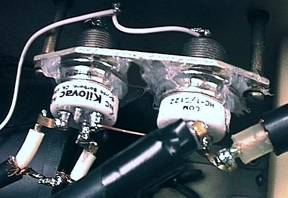
At
left two Kilovac
vacuum relays installed in an amateur gear. At right a
closeup on the open frame vacuum relay used in a QRO HF-2500DX
amplifier that can be equipped with a vacuum relay QSK
at extra cost. |
|
Note
that due to the slowness of some T/R switches many amplifiers
are often unable to operate fast QSK. For these gears some
manufactuers like Ameritron
provide an external unit called a "PIN diode QSK switch".
This small backbox is inserted in your RTX chain in front of your
amplifier and handles 2.5 kW PEP.
Next
chapter
Power
supply
|