|
|
|
Basics of antennas
Bandwidth (II) Several factors determine the bandwidth of an antenna. The main factor is the size of conductors used to build the antenna. If you made an antenna with electrical wire (that we can see as a small diameter tubing), it will display a shorter bandwidth than an antenna made of large tubing. A G5RV dipole for example, made of a copper wire can work in the phone band, as well as in the CW band, but not in both without adjustment of the antenna tuner. The same way a multi-band vertical or dipole on which are inserted trap coils to cover several bands will display a narrower bandwidth than using quarter-wavelength stubs as do some manufacturers. Stubs present the advantage to loose less energy than traps and help to keep the SWR low over a larger bandwidth. This is the outside diameter of conductors that determines losses as the RF energy travels only inside or outside of the wire. Another advantage of using large conductors size is they are more secure as they allow to transmit more energy, more powerful signals safely without risk to warm or worst, to burn the conductor. We can explain this effect in another way. If you work with a high SWR over 1.5:1 on the transmission line, your antenna begins to loose some energy (about 1/20th) and is no longer performing efficiently. This effect means that the amount of energy you keep for transmit while keeping your SWR under 1.5:1 will be used to cover some extend on the band. This size represents your antenna bandwidth. All antenna manufacturers and designers center the lowest SWR reading on the center of the band the most used, for example 14.2 MHz in place of 15 MHz, where most antennas display a SWR from 1:1 to 1.5:1 in average. However a few hundred kHz away, at the beginning and the end of each band the SWR exceeds often 2:1. Cushcraft R6000 vertical for example covers all bands from 6 through 15 m with a SWR under 2:1 and a bandwidth over 1700 kHz on 10 m. However Cushcraft cannot keep the SWR under 2:1 over 100 kHz on the 17 m band.
Do not confuse either the bandwidth with the gain of your antenna. Larger sized tubing or wire does not provide more gain, it only open your bandwidth and handles more power. At last wire antennas or beams can perfectly be resonant even on bands for which they are not cut for... I personaly experimented such a case using a 3-bander Fritzel beam working on 20, 15 and 10 m bands that I perfectly matched with a Yaesu FT-1000 MP Mark V and an external SWR-meter on the 17 m band... Don't ask me how is it possible, what magic matching box did I use, but it worked, and many amateurs can confirm this fact. Polarization We introduced in the first pages dealing with the radio propagation that an electromagnetic wave is made of two fields, the electric and magnetic fields that move together. Using radio waves, it has been arbitrarily defined that this is the electric field position and direction with a reference plan (to the ground on the earth) that determine waves polarization. Thus, when the electric field is parallel to the ground, one say that the wave is in a horizontal polarization. If the electric field is perpendicular to the ground, one say that the wave is in a vertical polarization. Usually the electric field is moving in the same plane as the antenna elements. If you work with a dipole tight horizontally and fed at center, then the polarization is horizontal. The field is vertically polarized with a vertical antenna. What is its effect on the properties of antennas ? To work properly transmit and receive antennas must have the same polarization. If they don't work in the same polarization plane signals will extinct like using a polarizing filter : you will record a reduction of about 20 dB compared to a signal working in the same polarization, and even more on low frequencies (3 MHz and down) due to absorption. This loss represents a decrease of about 7 times of the signal power. So to prevent such losses some users install their dipole or beam at an angle of 45° in respect to the ground to achieve the best compromise between both polarizations. It seems that this solution works rather good.
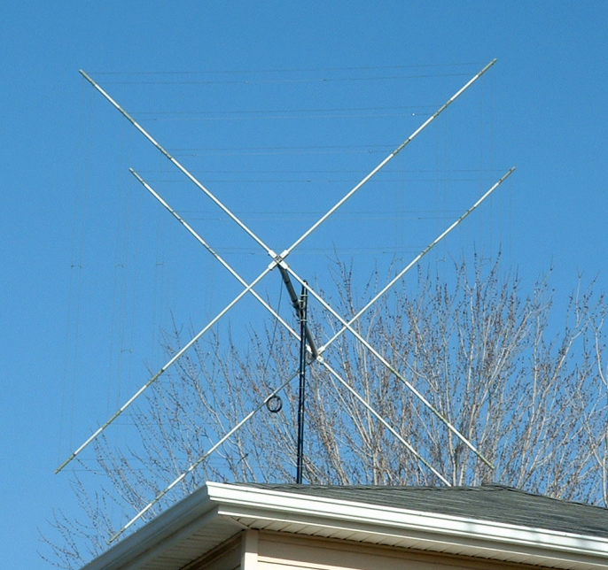
To prevent a polarization mismatch that can also occur during geomagnetic storms, the best way to work is using both vertical and horizontal elements. They will radiate in phase and the resulting polarization will be the contributions made by each set of elements. In this case the polarization is told linear. When the vertical and horizontal elements are fed out of phase the resulting polarization is either elliptical or circular. With circular polarization, as seen in front of the observer, the wave front rotates every quarter period between vertical and horizontal, making a complete rotation (360°) once every period. You can select your antenna to spin your waves clockwise or counter-clockwise. This phenomenon has no effect on the field intensity as it is equal to all instantaneous polarizations. A circular polarized aerialis usually designed in shape of an X or in helix. The first displays simultaneously a left and a right polarization (LCP and RCP). By design, like a screw thread or a spring, the helix is either LCP or RCP. It offers the advantage to be a broad-band antenna by design eliminating SWR problems that always stay between 1:1 and 1.15:1 with an input impedance near 140 ohms. The circular polarization is mainly use for space communications between 144 MHz and 1 GHz where it helps in reducing the rotation phase at reception and signal fade (QSB). This method increases also performances in DXing. However due to bulky none HF stations and few V/UHF ham installations are equipped of crossed Yagi's or helical antennas. If you are fan of weather images, astronautics and space missions, you can take advantage of stacked helical antennas (quadhelix) or, better, use small dishes tuned in the S-band between 2.2 and 2.3 GHz, range of frequencies in which most satellites and spacecrafts download their data to ground installations (downlink) since the first Apollo missions. If you are interested in this activity refer to the AMSAT website for more detail. At last note that working with harmonic wire antennas like V dipole or rhombic (a diamond-shape wire antenna), the polarization becomes elliptical. To be complete, remind that theoretically, if elements of a Yagi should have to be perfectly aligned in the same plane to work correctly, facts proof that some twists in an element are without effect. Indeed, tests have been made by Kent Britain, WA5VJB, with a UHF antenna showing that a tilt of each element up to 20° relative to the driven element does not provide any measurable effect on working conditions. So don't worry if your elements are slightly bent or not perfectly aligned; at that scale, for dame nature it's the same ! Ordinary and extraordinary waves Another event, much less know by amateurs can change the polarization plane. When radio wave reaches the ionosphere it splits in two characteristic waves, the ordinary and the extraordinary waves which travel independently through the ionosphere. These waves show an elliptical polarization. If the electric field (that we can see as a vector perpendicular to the direction of travel) rotates clockwise as the wave progresses, we speak of ordinary wave, if it rotates anti-clockwise we speak of extraordinary wave. The direction of rotation depends on the orientation of the raypath relative to the direction of the geomagnetic field. If the vector keeps a constant length (amplitude) as it progresses we are in the special case of a circular polarization. At last a polarization change can also be induced when plasma clouds or some objects reflect sky waves that see their field change of polarization. As the sense of polarization is often at the origin of confusion, it as been defined that for a fixed observer looking in the direction of the geomagnetic field, the electric vector of the extraordinary wave rotates in a clockwise sense, regardless of whether the wave is coming towards the observer or going away. Except the problem of attenuation and the famous fading, this polarization flipping explains also that sometimes you hear loud and clear a station and that at another time the same station arrives very weak : there are some chances that it is because the polarization changed in the course of the propagation what reduced the amplitude of his signals. But as many other causes can generate these attenuations and that sky waves can usually reach your antenna according several angles and modes (reflection, refraction, etc), in HF it is not necessary to work with crossed-elements, all the more that the choice of polarization is also determined by other factors like the size of your beam, the height of your support or even the polarization of near RF noise sources. That said, most DXers will tell you that they work in horizontal polarization. The main reason is that experimentally we discovered that this plane is generally more quiet. Why ? Because most man-made noises (QRM) come from devices used by people living in buildings, located at ground level or in the air (airplanes) and are thus vertically polarized. But this subject is quite complex. More will be told about polarization mismatch when we will discuss about ionospheric perturbations. Last chapter
|
||||||||||||||||||||||||||