|
|
|
All about Lightning protection
Identifying assets to protect (II) To avoid spending too much money in a lightning protection system, usually we need to identify the assets to protect in creating a priority list. It will contain if not all, at least the most expensive or important radio equipments installed in your ham shack that you want to protect against lightnings. The ones that will stay without protection would be unplugged for security as soon as a thunderstorm will approach within 10 km (6 miles) of your area. Begin with your more expensive gear, probably the transceiver, then its power supply, your HF amplifier, the SWR-reader and possible scope, the rotator control box, the packet interface, etc. After a first identification of all big and expensive devices you have to look closer and identify also all accessories attached to these devices, the key, the coax switch, the external speaker, maybe some CW filters, etc. Then examine each unit and list its connections, the I/O lines in both input and output, without to forget of course the feed line coming from the antenna and maybe the rotator control cable. Then proceed the same way with all other equipments installed in the ham shack : your computer and all its wired peripherals, including the screen, the keyboard, the modem or the DSL connection, the optional printer, the scanner, etc. Add to the list your stereo system and its wired connections and maybe your TV, the telephone and its answering machine and a digital clock. Don't forget the secundary power supplies that recharge your GSM or your digicam as well as all external input devices permanently attached to your computer like the mouse, the memory card reader, an external DVD reader, maybe a router or a Wi-Fi station, etc. At
last do not forget to draw a ground line from the chassis of each
metallic gear, from the transceiver, the amplifier, the
tuner, etc., to the outside of the diagram. For more clarity I have
represented them with a small ground symbol ( Excepting if it is integrated in your rack, do neither add the lighting to the list nor any other domestic device like the frige or the alarm system. For this first installation we focus only on the radioelectrical equipment that you use in the ham shack because it should protected by a grouding system independent, but bonded to it later, from the domestic grounding system.
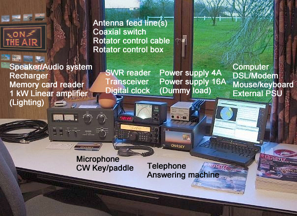
For this case study I took my own small ham shack as practical example. As you can see it exceeds rapidly 20 gears and this one does practically include no workshop equipment (no oscilloscope or any other test or measurement device). This is really a very simple installation that most active amateurs know probably very well. But how to remember all their I/O circuits, their indivual power requirements to purchase the suited protectors ? It is simple. We are going to place all these equipements and their I/O lines in a block diagram. This drawing will represent the electrical circuit that the lighnting might potentially follow to destroy your equipement if there is an entry point of less resistivity. Therefore you must include in this diagram all devices to protect and all electrical connections made between them. Represent each device by a rectangle and write its name inside. Represent the wires by simple lines. Do not forget to draw a ground wire from the chassis of each equipment. Even passive components, USB devices and the antenna coaxial switch must be included in the diagram. Knowing that a lightning can jump from one metal object to another within a radius of 1.2m (4 ft), insert also in the diagram all metallic devices located within 1.2m around your radio equipement. That can be a metallic frame, a metallic desk or a chair, a metallic bin, a telephone or even the case of your computer. Don't forget any device because the lightning is very clever to find the least weak point of your radioelectrical installation and the path of least resistivity. Then project all I/O connections and feed lines, what we call the circuits, to one side of the diagram for a better clarity. Align them along a bus as displayed above. In addition, on each feed line write the maximum power sustained, the range of frequencies, the type of feeder, the type of connector and its gender if required (i.e. Coax, PL-259, 1kW, HF). At last, circuits side and close to each I/O device write the voltage and current requirements (i.e. 220 V, 2A). These indications will help you later to select the appropriate protector. When your diagram is complete, reflecting all electrical devices and I/O of your ham shack verify each of them to check if you don't forget a connection or left a peripheral aside. Once done, take your largest red pen and draw a large frame around all devices. All wires entering this frame must be protected ! In identifying all devices and I/O lines of your ham shack, you have already realized 1/4th of your project. But we have still to protect each of these devices with a good system, then create a single ground point and bind this "point" to a ground system located outdoor in order to dissipate the lightning energy away from the house. Let's examine each step separately. Identifying and protecting I/O lines Until now a surge can easily reach each device installed in your ham shack in following simply either your coaxial, the telephone/DSL line or the AC line if they are not properly grounded. As we told, dame Nature is smart enough to find the path the least resistive like water find always the lowest point. A lightning protection is in fact very simple. In case of threat on one of your device, if the voltage suddently increases for example or if appears a point of lower impedance, it purposes is to short-circuit the entry conducting to this device, and this for all gears installed in your ham shack. But not necessary in the same way. If the individual protector can be a simple electrical component like a shunt device, its sensitivity is of the uttermost importance to protect your assets. Indeed, like you cannot block the water flowing in your sink with a too small stopper, you cannot install any kind of protector on your devices.
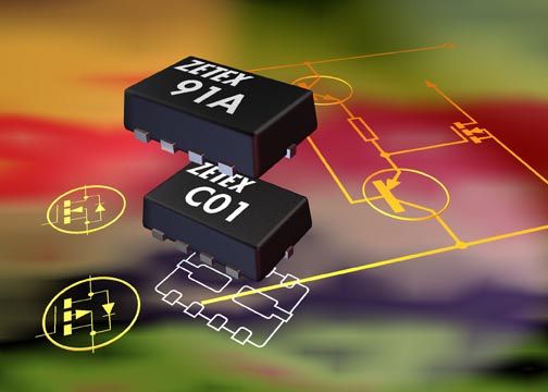
The front-end stage of a transceiver for example consists in FET transistors like the ones displayed at left from Zetex. These small components are known to be very sensitive to overdrive (i.e. high VSWR). They display in fact a maximum tolerance just a few volts above the operating value. The I/O ports (serial, etc) of you computer are also very sensitive and it happened that plugging simply the mouse in its port, amateur short-circuited their mother board. That means that the protector must be selected with a great attention to let pass through the least energy as possible in respect with the specifications of your device. Find the proper protector capable to limit the lightning discharge is your first objective. Manufacturers sold probably as much protectors as there are devices to protect, or almost. They come in different shapes, several range of frequencies, suited for AC or DC power, Telco, IT network, in single or multiple circuit lines. We must thus well defined our scope. We can divide protectors in five major categories : - The coaxial surge protector - The AC power protector (most devices powered on main) - The Telco protector (for the telephone, modem, ADSL, etc) - The circuit breaker (a shunt for all external devices, i.e. the antenna rotator or elevator) - The ITW Linx surge protector and alike (for IT networks in UTP) The coaxial surge protector Sometimes called a lightning arrester, the coaxial surge protector is designed to join two segments of coaxial cable. Inserted in-line on your feeder it protects your antenna. A quality product should not add to system neither SWR (the worst display a VSWR 1.2:1), nor insertion loss, nor return loss and it must operate in a wide range of frequencies and be compatible with your emitting power, match to the load and using the right connector type (i.e. 1.5-50 MHz, 2 kW, 50 ohms, SO-239). Note however that some models are not suited for transmitting or do not provide both gender M/F. Of course like most protectors there are two sides, to not reverse if you want that your protection works properly !
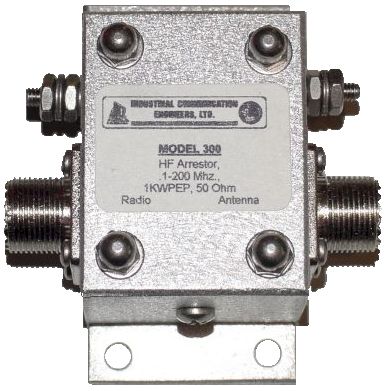
Dipole feeded with an open-wire must be protected in another way, using a shunt-type protector for example instead of an in-line model. How that works ? Use two identical gaz-tube surge protectors and install them at each leg of the feed line near the entry point (usually approximatively 10m below the dipole). Most are capable to sustain a current peak of 40-50 kA (on 8/20 mS IEEE standard) and voltage exceeding 1000V. They work in frequencies ranging from DC to 2 GHz, they provide a bi-directional protection and are weatherproof. Aside the HF, V/UHF or broadband surge protectors, there are models specialized for repeater duplexer antennas, GPS, radio, TV, CCTV antennas, etc. They are usually available with a flange or a bulkhead mounting like the model displayed above, allowing to screw it easily on the single point ground plate (see below). The AC power protector This is a protector well know by amateurs and other handyman. Most devices of your shack are probably powered on the main, 220V or 110V. Like the telephone outlet, the AC power outlet is specific to each country due to the non-standardisation of the connectors at worldwild scale. So you must buy it in your country to prevent any hardware compatibility problem. But this is not enough. Many "AC Lightning protector" are not what they claim to be but simple outlets protected against voltage surge, sometimes coupled to an uninterrupted power supply or even simple multi adaptors equipped with a power switch. If some use a safety ground wire, this latter is unable to carry away the surge of a lightning strike. Even a ground wire made of #14 AWG is too inductive with respect to the short interval during which the current intensity "explodes" in a strike. None of these products will never protect your equipement excepting against line noises.
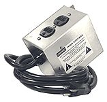
A good AC power protector able to redirect the RF energy of a strike to the ground must be placed in-line with your device and protected with a metallic housing to avoid melting under the strike conditions. It must match your voltage and current requirements. In my block diagram there are 7 devices powered on 220V at 2A maximum, plus the transceiver and the amplifer that draw each 220V at 16A maximum. You can combine all small devices powered under 220V at 2A maximum on a single AC power line protector. You can combine them up to the limit of the circuit protector current limit (usually 15 or 20A in using a model similar to the one displayed at right). Once protected, the AC power can then be distributed to each of the equipment elements using a multi adaptor optionaly equipped with a switch. Drawing high current, I would recommend a separate protector for the amplifier power feed (15A) and another similar protector for the transceiver. Some high-end equipements might require a more powerful protector, up to 200A. At last GPS, TV, CCTV and other repeater feed lines require also a dedicated AC or DC protector able to separate the RF energy form the current and protect each device in respect to its requirements. The Telco/datacom protector Like the power outlet seen previously, the telephone line connector comes also in many types specific to each country. There is also technical differences, to name the classic old POTS to the digital terminal including a built-in answering machine or a video system. The oldest use a balanced line powered at -48V DC while modern devices are powered either via the line or on the main. Depending the model, an in-line DC protector (for POTS) or an in-line AC power protector (for devices powered on 220V AC) will be effective.
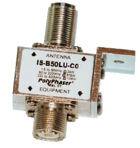
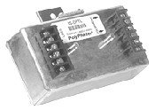
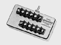
This telephone line will be probably also used for the asynchronous modem or your DSL connection. Most of the time these interfaces use modular connectors RJ-11 or RJ-45. Using a plastic housing, from an electrical point of view these connectors are very fragile and they cannot sustain the surge energy of a lightning strike. In such occasions either the connector is welding or is fusing. At last, plugged in an interface card, in case of surge these connectors can short-circuit, burn the printed circuit boards, and create arcs on equipements. So, as long as you can, avoid using these connectors and select a telephone line protector accepting bare wires like the model displayed above. This model protects also DSL connection or your UTP home network. In case of technical problem, call your phone distributor for help. The circuit breaker All devices located outdoor must also be protected, beginning with the antenna rotator and maybe the antenna elevator. The rotator of the antenna system can be driven by a relay, an electronic system or even optical encoders in the most advanced systems. Each model requires an in-line shunt device appropriate to the type of interface and voltage requirements.
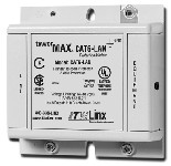
The network surge protector Although not all amateurs have installed a computing network at home, many amateurs use at least one home computer and maybe a portable. If you connect your computer to a network, there are some chance that you have selected a UTP (unshielded Twisted Pair) architecture. Of course, like the computer installed in your shack, its I/O must also be protected. For an ordinary 10/100 Mbits UTP network, ITW Linx and Tripp-Lite provide what they call a Category-5 LAN cable. This is a protector to wire in serie with the network and grounded the same way as the other protectors. Recently ITW Linx introduced a surge protector for routers too, a category-6 model. Next chapter
|
|||||||||||||||||||||||||||||||||||||