|
|
|
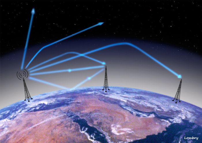
Space Communications with Mars
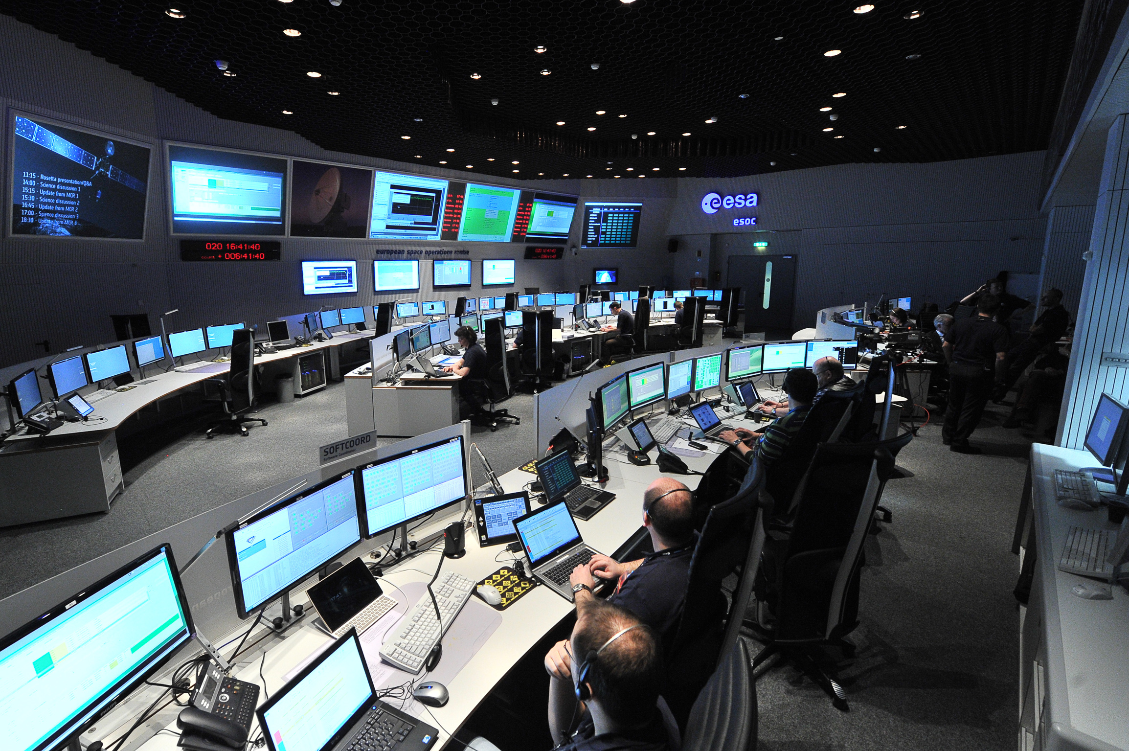
The rovers and orbiters of martian missions (I) In the years 90's, NASA developped its first deep space communication network, DSN, to keep control of space probes that they have sent in exploration missions to Mars and to the other bodies of the solar system. Recently, the agency used this powerful system to communicate with rovers Spirit, Opportunity and Curiosity that landed on Mars, the orbiters MGS, MRO and other Mars Odyssey, the Huygens lander that visited Titan and New Horizons that visited Pluto among other space probes. Take this "opportunity" to wonder how scientists manage telecommunications with the space probes exploring Mars. What antenna systems do they use, on what frequencies do they work, what are the specifications of these radio equipments, at what rate data are transmitted, and what are limitations ? Advantages and drawbacks of shortwaves Radio amateurs know that by nature signals transmitted on HF bands (1.8-30 MHz) at low incidence have difficulties to pass through ionospheric layers surrounding the Earth, whether they are transmitted from the ground or from space. Under some conditions, these regions of high electronic density act like mirrors for radio waves. If it is a huge advantage for ground stations who wish to communicate with remote stations (by bouncing successively between the ionosphere and the ground, HF waves can reach DX stations), for the same stations wishing to communicate with satellites moving into space it is rather a big problem... How to explain this phenomenon and how can we in spite of everything communicate with satellites and spacecrafts ? The cut-off frequency We explained in the chapters dealing with the radio propagation and ionospheric perturbations that the ionosphere is a mixture of plasma and atoms more or less ionized by the solar UV radiations. Between the D- and F-layers its density varies between 10000 and 2 millions electrons/cm3 and falls down of approximately a ten-factor during the night, and is not even measurable any more for the lowest layer. The maximum usable frequency, MUF, strongly depends on the ionization level of the F-layer. During high solar activities, when the number of sunspots exceeds 200 or so, the MUF rises easily to 50 MHz at daytime. However these conditions change permanently during the day with a progressive decrease of MUF and LUF during the night. There is however a cut-off frequency fp for the ionosphere beyond which it loses its capacity to reflect shortwaves. Depending the latitude, the season and the solar activity mainly, during the day this frequency is around 3-10 MHz and goes down to about 2-6 MHz during the night, according to the next formula, in which fp is expressed in Hz :
with Ne, the electron density; e and m, the charge and mass of the electron and εo, the free space permitivity. We can also use a simplified formula : fp (MHz) = 9√e This frequency is valid for a HF signal radiated vertically. As soon as the incidence of the signal is tilted (what hams seek to reach DX stations) the frequency increases proportionally with (1/cosθ), θ representing the incidence angle with the normal. Thus if the signal is emitted at 45°, the cut-off frequency of 10 MHz goes up until 14 MHz, etc. Extrapolating these properties towards higher frequencies, one notes that signals transmitted in V/UHF and SHF bands easily pass through the ionosphere, except at grazing incidences (when cos θ is very small).
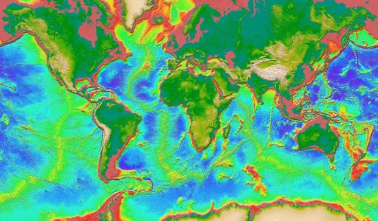
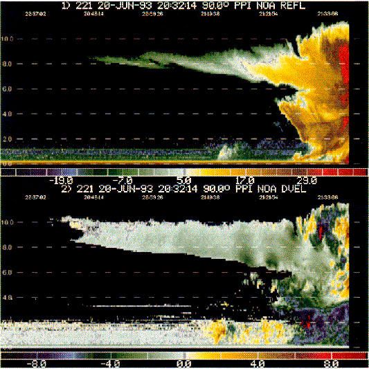
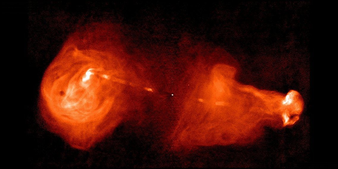
Note that between 1-90 MHz the behavior of the ionosphere as mirror for shortwaves is rather complex, with both reflexions and attenuations of the signal quite important. But the ionosphere is not completely opaque to HF waves. Like a window, when the incidence angle is very wide (wide compared to the normal), the waves are completely reflected by the surface which acts like a mirror, while when the waves travel perpendicular to its surface, they are able to entirely pass through it. When the angle is perpendicular to the ionospheric layers one can thus pass through the ionospheric layers at frequencies lower than the MUF, especially in time of low solar activity. This principle was applied successfully to several ham satellites such Radio Sputnik and Amsat Oscar in the years 1970-80, some of them sending HF beacons or CW telemetry signals in mode A, downlink on 29 MHz (towards the Earth) and even on 21 MHz. But to work in this way is not without drawbacks, and at daytime transponders of these satellites are affected by the F2-layer ionization during periods of high solar activity. HF is thus not the panacea to work by satellite. Background noise One also notes that in the UHF bands radio waves carry many interferences and various noises which are superimposed on signals. That starts in the long waves (LW or AM) with atmospheric noises (thunderstorms, etc), that extends to the VHF, sensitive to meteors ionization trails and auroras, to attenuate towards approximately 500 MHz. It is thus necessary to go up in frequency to cut off from these problems. But the Sun and thunderstorms are not the only elements that scramble space communications and more one goes up in frequency more one records a background noise which is in fact related to the gamma radiations emitted by galactic and extragalactic sources (stars, supernovae, etc). On the other hand, more one goes up in frequency and outside the gamma emission lines, the Sun influences on the wave propagation weakens. Bandwidth Beside these two problems of propagation and noise, one also notes that using SHF bands (2.9-30 GHz) rather than HF for space communications, not only the noise level and interferences are much weaker there, but at these centimetric wavelengths one can use very directive antennas and broadband emitters to transmit high volumes of data. Indeed, to fasten transmissions of large volumes of data without error, it is necessary to work with bandwidth of several megahertz. It is thus impossible to work this way on HF (a signal uses 3 kHz in phone and 1 kHz in Morse) because the signal would occupy all the HF spectrum and would make it unusable for any other application ! It is the same problem that encourages hams to fight against BPL, connecting Internet users by broadband signals on shortwaves. Taking all factors together, one understands better for which reasons, if we want to pass through the ionospheric layers by the means of shortwaves, we must use higher frequencies, which wavelength is insensitive to the electron density but also free of interferences and suited to carry high rates. The X-band For space communications the main frequencies bands that we can use are microwaves and particularly the S-, X- and K-bands at a few GHz, which represent a wavelength of a few tens of centimetres maximum. Beyond ~20 GHz other problems arise like the atmospheric absorption due to clouds and rain. The S-band near 2 GHz is first of all used by ships at sea (e.g. radiolocation and radionavigation) as well as for GSM, Inmarsat and DCS communications. The X-band is the favorite frequencies band used for many commercial and scientific transmissions : small and large dishes tuned on X-band between 10.7 and 20 GHz are used by satellite TV, in geodesy (e.g. TOPEX oceanographic applications), in meteorology (e.g. polarimetric radar, similar to lidar) or in radioastronomy (e.g. deek sky objects study like quasars jets). At last, some advanced radio amateurs do not hesitate to use these high frequencies for Moon bouce activities (EME) or to work with some satellites (see bandplan).
The X-band is so crowded because basically its main advantage is to be within the reach of everybody, and it can be used with small antennas, low power and relatively simple equipement compared to AM or HF installations for example. This band of frequencies is also less perturbated (QRM) and allows the transfert of huge volumes of data. At last used with digital networks and high powers it is less sensitive to phase rotation. Amateurs have rapidly profit of these advantages in launching thanks to ESA the small AMSAT OSCAR 13 (AO-13) satellite in 1988 equipped of transponders that operate in B-, S- and L mode, at respectively 435/145 MHz, 435/2400 MHz and 436/1269 MHz (at 2 m, 70, 24 and 13 cm). At first sight, many X-band applications work by satellite. Indeed, at a few GHz waves propagation does not exactly "work" like long waves (AM) or even like decametric or V/UHF wavelengths. Due to their short wavelenghts, signals are quickly disturbed by usual obstacles like buildings or mountains. And as we told, they are also reflected by ionization clouds (auroras, meteor trails) and particles in suspension in the air (dust, rain, snow, hail). X-band antennas are thus first of all directed toward space, to artificial satellites, to the Moon and to the deep sky objects, including for emission purposes to probe the ground and the underground of the Earth, and to communicate with satellites. In most cases, professionals have upgraded somewhat this equipment for space telecommunications to powers of a few kilowatts and use parabolic antennas (dishes) of several meters in diameter.
But for the space science department of an university a 5m dish as well as a suited radio equipment able to track satellites are tools very expensive to maintain and many of them rely on smaller solutions. Only a public agency like NASA's JPL or its partners in Europe (ESA), Russia (IKI), India (ISRO), Japan (JAXA) or China/Taiwan (CASC, NSPO) can support such investments, even if about ten other countries master the space technology (Brazil, Canada, Israël, Pakistan, Ukraine, etc.). It was thus not surprizing that JPL's engineers have developed this technology for space communications too, to control spacecrafts that NASA has launched through the solar system and beyond. Today the X-band allows astronomers to make very accurate measurements on very far targets, which distance can exceed tens of millions of kilometers for planets. Such antennas are also capable to receive data from spacecrafts traveling at the borders of the solar system in the case of Pioneers and Voyager's, today quasi out of the solar system, or straight out from the deep sky when they study radiations emitted by quasars located at a few billions light-years away... Next chapter Tracking the spacecraft cruise
|
||||||||||||||||||||||||||||||||||