


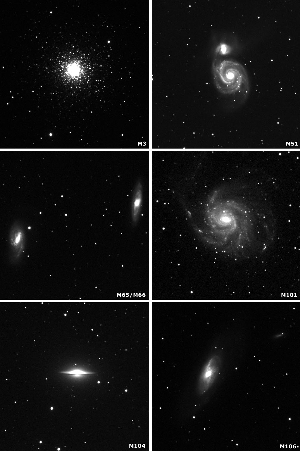
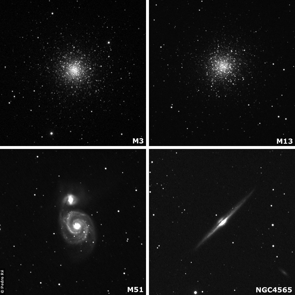
M3 C14 ST7 (15Sec, 30Sec, 60Sec, 120Sec)
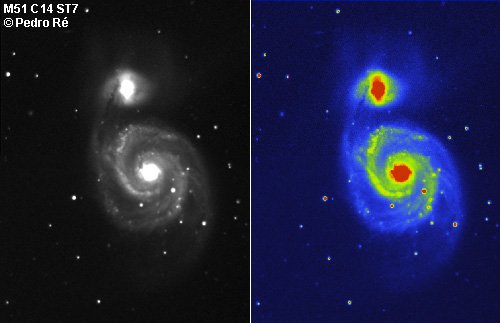
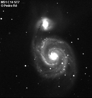
M51 C14 ST7 (10Min 5x2Min Addition Mosaic)
M51 C14 ST7 (6Min 3x2Min Addition Mosaic )
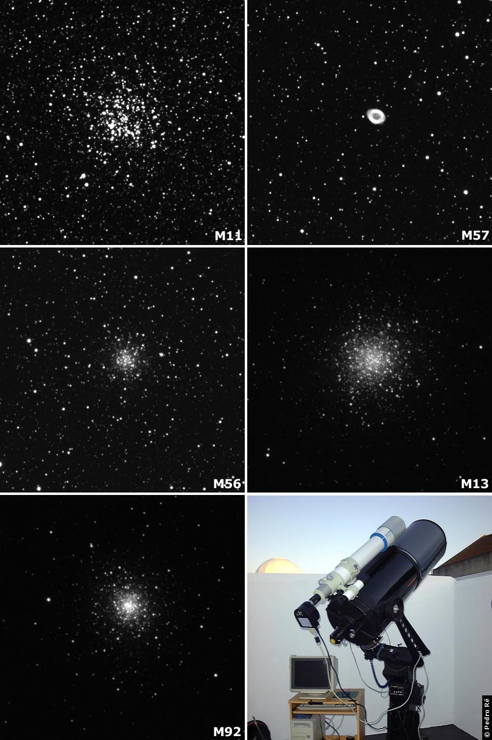
M57 C14 ST7 (10Min 5x2Min Addition 1x1 binning)
M57 C14 ST7 (15s, 30s, 60s, 90s, 120s, 10Min)
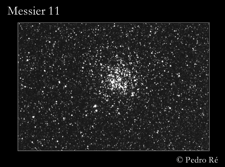
M11 C14 ST7 (5s, 10s, 30s, 60s)
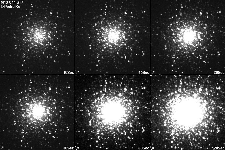
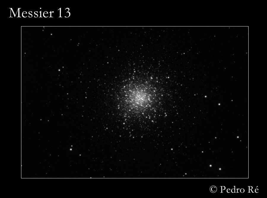
M13 C14 ST7 (10s, 15s, 20s, 30s, 60s, 120s)
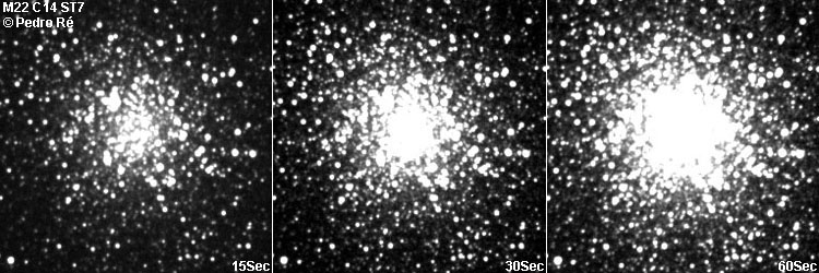
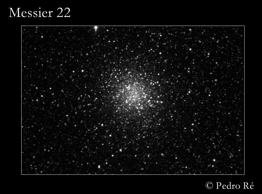
M22 C14 ST7 (15s, 30s, 60s)
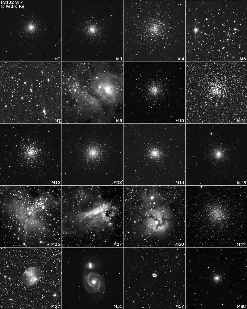
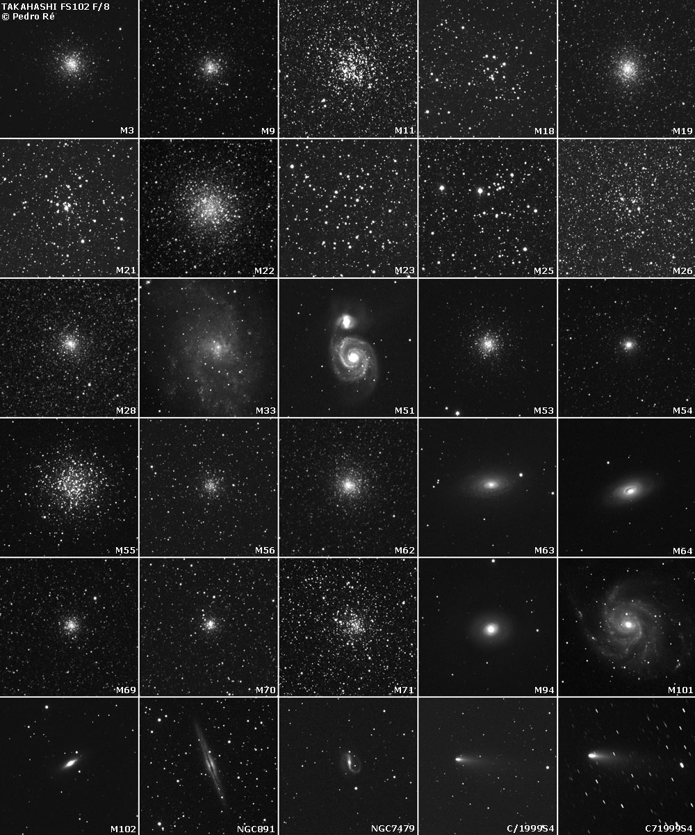
M51 FS102 ST7 (30Min)
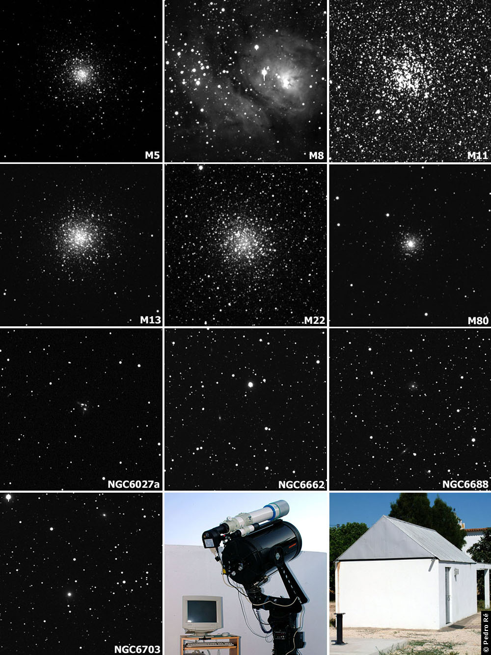
M11 FS102 ST7 (3x2Min Addition)
M13 FS102 ST7 (3x2Min Addition)
M22 FS102 ST7 (3x2Min Addition)
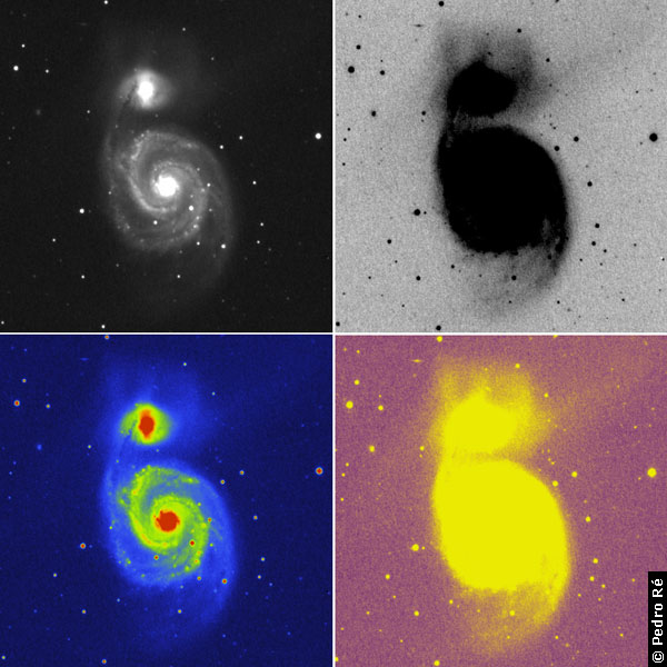
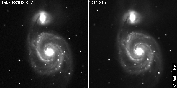
M51 Comparison images FS102/C14 ST7
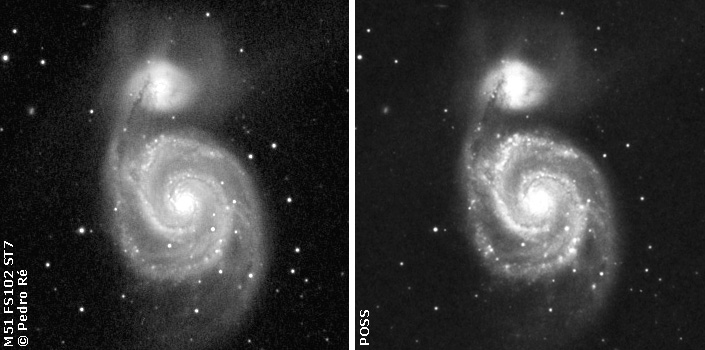
M51 Comparison images FS102/POSS I
 |
Deep-Sky images (Takahashi FS102 + ST7) |
 |
Deep-Sky images (Takahashi FS102 + ST7) |
 |
Deep-Sky images (Takahashi FS102 + ST7) FULL MOON |
 |
Deep-Sky images (Takahashi FS102 + ST7) |
 |
Deep-Sky images (Takahashi FS102 + ST7) |
 |
Deep-Sky images (Takahashi FS102 F/6 + ST7) |
 |
Deep-Sky images (Takahashi FS102 F/8 + ST7) |
 |
Deep-Sky images (Takahashi FS102 F/6 + ST7) |
 |
Deep-Sky images (Takahashi FS102 F/8 + ST7) |
 |
Deep-Sky images (Takahashi FS102 F/8 + ST7) |
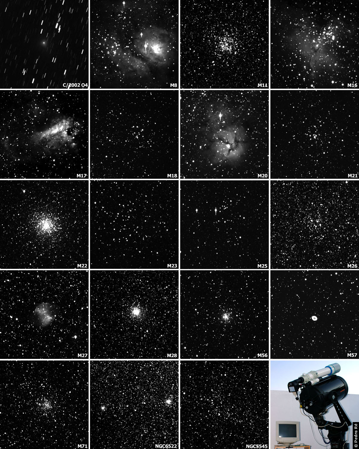 |
Deep-Sky images (Takahashi FS102 F/6 + ST7) |
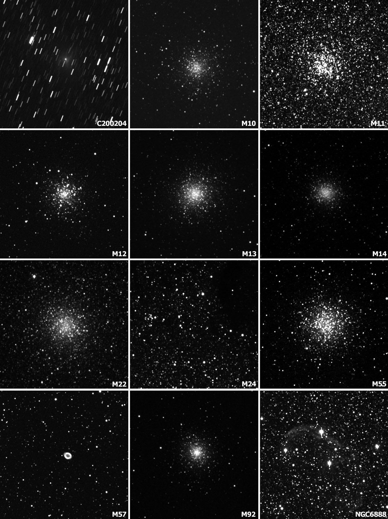 |
Deep-Sky images (Takahashi FS102 F/6 + ST7) |
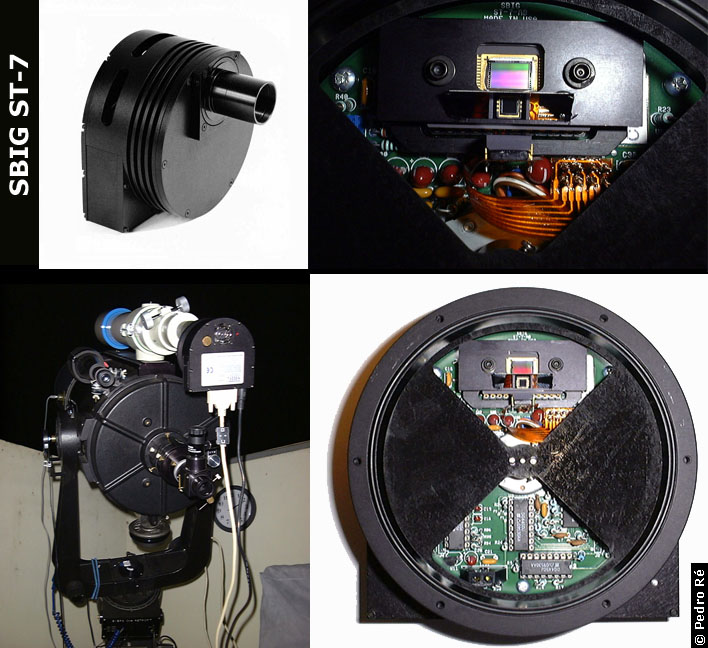
The Model ST-7 is a multi-purpose instrument which feature a unique two CCD arrangement in parallel. This arrangement permits:
1. When used with a personal computer (Macintosh or PC) can function as an integrating, cooled CCD camera to capture monochromatic images of very faint objects. Carefully designed for astronomical and scientific imaging.
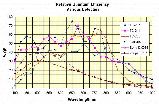
The ST-7 camera head incorporates a Texas Instruments TC-211 and the Kodak KAF-0400 detector which permit simultaneous guiding and imaging thereby eliminating the need for optional guide telescopes, or off axis guiding hardware to accomplish CCD imaging. Also this eliminates any possibility of guiding errors caused by differential flexure of guide telescopes or mirror shift.
 |
-
Horizontal: 57.3/Focal Length of Objective (mm) * 6.9
Vertical: 57.3/Focal Length of Objective (mm) * 4.6
3. When the camera (controlled by a personal computer) is installed on a photoguide telescope, or at the guide port of an off axis guiding device can detect any deviations in tracking of a telescope (in both axes), and then send correction signals via a relay cable to a telescope drive corrector controller; all of this is done with a better frequency, higher accuracy and over a longer period of time than most humans can perform. All of this resulting in professional quality astrophotographs limited only by the quality of the telescope, and atmosphere.
4. The SBIG ST-7 (or ST-8) instrument will accept the new S.B.I.G. Adaptive Optics technology (becoming available in early 1997) to reduce the adverse effects of atmospheric turbulence during astronomical (or possibly terrestrial) imaging. There is no other production CCD instrument that will accept this coming option.
The ST-7 camera head features a female "T-thread" which accepts a variety of adapters to attach the head onto a telescope, microscope, or other system. Furnished with each head are a male nose piece of 1.25" diameter (threaded to accept filters), a nd another of 2" (threaded for 48mm filters). A quiet, no vibration fan vents at the rear of the head to assist with the cooling functions. Connectors on the head are a female 5-pin DIN for power, a male 25 pin "D" to a computer parallel port, and a femal e 9 pin "D" connector to the telescope drive corrector/hand corrector for autoguiding or to an optional Color Filter Wheel. Included cables are the 25 pin "D" female to male, a male to male RJ cable with an adapter for the female RJ to male 9 pin "D" adap ter. A power supply is furnished (standard 115V or optional 12 V.D.C.).
THE ST-7 STAR TRACKER FUNCTION: Continuing their tradition of innovation, in October 1994 SBIG introduced the ST-7 (and ST-8) cameras with an unique concept (Patented) for astronomical imaging: each head contains two CCD's in parallel; a Kodak KAF0400 for imaging, and a Texas Instruments TC211 for tracking.
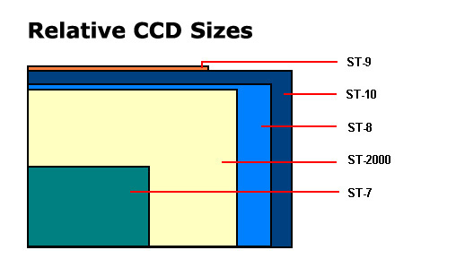
The two CCD's are mounted onto a common pedestal on top of the thermoelectric cooler within the CCD head housing. These CCD's share an Analog to Digital converter, and other readout electronics. In operation, the TC211 portion of the CCD camera detects a star slightly outside the field of view of the Kodak imaging CCD chip, and it generates the signals which then drive the relays thereby adjusting the telescope tracking. The geometry of the Model ST-7 is illustrated in Figures 2 and 3. The ST-8 concept is similar but, the CCD imaging area is larger than that of the ST-7.
The TC211 is identical to the chip used in the popular SBIG Model ST-4/4X guiding systems, and in practice the ST-7 tracking technique is very similar to the ST-4, except the ST-7 integrated concept has evolved to allow the TC211 to acquire and guide on fainter stars. In practice, up to the evolution of these cameras users have employed two separate CCD systems; one for guiding and another for imaging. And up to the introduction of the ST-7, no one else has rendered it successful within one single head th ereby allowing quicker and easier setup and operation, less complicated cabling, and simpler computer and power requirements.
The chip arrangement within the model ST7 CCD head
The camera head incorporates two CCD detectors, each consists of array elements, called pixels. The smaller array of pixels, arranged in horizontal ("X" axis) and vertical ("Y" axis) rows, convert photons (the light falling on the detector from a star) in to electrons. When a guide star's image is present at a specific pixel the micro controller will note the increased signal intensity from that pixel relative to the others. An indication of the intensity of the signal and the location (X and Y coordinates ) of the star on the detector are read on the control software display of a personal computer. As the telescope focuser is adjusted to improve focus (during the "Find and Focus" mode), more light from the star is focused onto a smaller area thereby increa sing the intensity which is indicated on the display as a higher value; this is an aid to obtaining precise focus of the star.
The Model ST-7 camera interface to the telescope consists of a cable from the normally closed/open connector to the telescope drive corrector or hand control. The camera will produce drive adjustments usually commanded by the telescope drive corrector pus h button switches. A manual override on the computer keyboard allows the corrections to be made by the user.
By making fine adjustments to the telescope via the computer keyboard, a guide star can be moved onto the detector, or even onto any particular pixel. However, a guide star does not have to be centered onto the CCD detector for the system to function prop erly. The user can select the length of the star tracker exposure times from 0.1 to 20 seconds (default is 1 second); so stars ranging over 10 magnitudes in brightness can be tracked without adding optional filters. The area of pixels to be used (guide bo x) can also be adjusted to accommodate very long focal length guide telescopes, or mediocre atmospheric seeing conditions.
AUTOMATIC DRIVE CALIBRATION:
Once an acceptable star is found, and when focus is achieved, the operator will select "Calibrate Drive" function so the CCD system will "learn" the characteristics of the telescope drive. The software sequentially activates relays via the camera head output which send a user selectable 1 to 10 se cond signal to the telescope drive corrector to move the telescope North-South and back, then East and West and back; the telescope will end up returned to the point at which it started. This function "teaches" the CCD system what commands will cause the telescope to move in what direction, and how fast. This calibration feature is invaluable when using a German equatorial mount, or an off axi s guider, where the proper direction can be very difficult to guess.
Then the operator will select "Track"; any drifting motion of a star across the CCD causes it to appear at a different pixel at each following exposure. The computer controlling the CCD will then calculate how far the star has drifted and generates a control signal, transmitted through the relays to correct the position. T he control signal, and its duration are a function of the star's position error. The camera system can take an exposure (integration), read out all the pixel values, and then calculate and transmit the necessary telescope correction in less than one second.
In the "Track" mode the camera acquires a fresh star image, centers the image on a pixel, and holds that star in position by constantly monitoring it - sending correction signals to the telescope drive immediately after the exposure. The CCD is thermoelec trically cooled to enhance its sensitivity to dim stars. This extreme sensitivity enables guide stars as faint as 8th magnitude to be tracked utilizing as small as a 60mm guide telescope. The rapid calculating power of the computer enables the guide star location to be determined within a fraction of a pixel, enabling better than 1 arc second tracking accuracy. An alarm signal is actuated if a guide star is lost.
SPECIFICATIONS OF MODEL ST-7 DUAL CCD SYSTEM DETECTORS
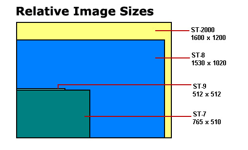
Imaging Resolution: 765 x 510 Pixels, Class I Kodak KAF0400 CCD
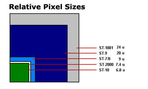
Imaging Pixel Dimensions: 9 micron square
Imaging Array Dimensions: 6.9mm x 4.6mm, 8.3mm Diagonal
Guiding Resolution: 192 x 164 Pixels, Texas Instruments TC211 CCD
Guiding Pixel Dimensions: 13.75 microns x 16 microns
Guiding Array Dimensions: 2.64mm square, 3.73mm Diagonal
SPECIFICATIONS OF MODEL ST-7 ELECTRONICS
Binning: 2x2 Noiseless/Software Selectable
Full Well Unbinned (in Ke-): 85,000
Full Well Binned 2x2 (in Ke-): 40,000
Readout Noise (in e-): 15 RMS Double Correlated Sampling
Dark Current: <0.2e-/pixel/sec @-10 degrees C
SPECIFICATIONS OF MODEL ST-7 HARDWARE
Desiccant: Yes, internal & replaceable
Standard Control Software: PC Windows or Win95
Communications Port: Parallel
Analog/Digital Converter: 16 Bit
Digitization Rate, Full Frame: 11.5 secs. at 33 KHz
Shutter: Electro-Mechanical
Fastest Shutter Speed: 0.11 Sec.
Longest Shutter Speed: 1 Hour
Cooling From Ambient: -35 Degrees
Power Requirements: 115V/220V AC Provided (12 v.d.c. optional)