by Christian Buil
The Solar Explorer - November 15, 2023
by Christian Buil
The Solar Explorer - November 15, 2023
Construction

Contents :
1 - A solution for every situation
2 - How to mount Sol’Ex
3 - How to adjust Sol'Ex
4 - Complements about assembly
Part 1: A solution for every situation
This page explains how to mount and adjust the Sol'Ex. This is the stage just before the observation that will give our Sun another face.
The Sol'Ex project is based on the "do it yourself" (DIY) concept. Everything is designed to help you get the job done, and there's no question of any obstacle to observing with Sol'Ex. So there's no need for you to have any optical, mechanical or computer skills, or to have any very special technical equipment (although, we admit, a few screwdrivers are necessary!). Curiosity is the key to success!
Sol'EX is based primarily on a fairly classic spectrograph optical design, but carefully studied to achieve high performance in a small volume. Shelyak can supply all optical components in kit form. See part 2 of the "Resources" page on this site.
Secondly, the optics are integrated into a 3D-printed mechanical assembly. Here you have two choices:
Choice 1: print the mechanical assembly yourself - you'll find all the STL files and explanations to make this possible below. Of course, you'll need a 3D printer and a certain amount of know-how. It's a great way to learn, but it's also fun and useful, because a 3D printer is always very useful. You can then customize Sol'Ex to suit your needs, to improve or adapt it. Sol'Ex is an evolutionary project, offering great flexibility. In doing so, you produce the initial, fully operational version of the Sol'Ex mechanics, known as version V1 (sometimes called "historical" or "original").
Choice 2: companies are able to print the V1 version of Sol'Ex for you, the STLs being public (but under copyright). If necessary, this relieves you of a task which we hope will not be an obstacle to benefiting from Sol'E. Among these companies, we should particularly mention Azur3DPrint (see the Resources page in part 2). Not only can this company supply us with the historic V1 mechanical kit, pre-assembled (inserts in place, screws and bolts...), with a fine finish, but also a version V2, which takes up all the codes of the V1, functionally identical, with a similar general appearance, but with a new design created by Azur3DPrint in partnership with the author. The "V2" brings a host of improvements that make it easier to use, and gives it a more modern look that enhances user comfort. This version is also pre-assembled, ready to receive the optics (note that the "original" V1 and "Azur3DPrint" V2 versions are perfectly compatible with the Shelyak optics kit).
Your next task is to assemble the components and adjust the optics. With a little method, this assembly/adjustment will take you no more than an afternoon. In the next section, we'll explain how to do it. Don't panic, you'll be guided step by step, and it's easy!
Part 3 : How to mount Sol’Ex
If you set aside the mechanical manufacturing part, the two remaining stages concern mechanical and optical assembly on the one hand, and optical adjustment on the other.
The following document is a Sol'Ex assembly manual (download in PDF format). This is a step-by-step procedure. Follow these carefully and everything will go smoothly:

The historical version (V1) and the Azur3DPrint version (V2) are assembled very similarly.
Part 3 : How to adjust Sol’Ex
After assembly, it's time for adjustment. Here again, we recommend downloading a PDF manual, with a continuum of simple steps to get your Sol'Ex fully operational:

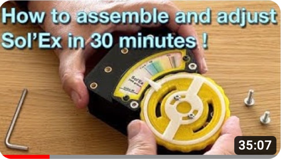
Normally, these brief documents are self-sufficient, but you can also watch a video that shows you how easy it is to set up and tune Sol'Ex in a very short time (click on the thumbnail):
Part 4: Complements about assembly
Here's a brief summary of these assembly steps, particularly useful if you're assembling from the historic Sol'Ex "V1" version. See also the YouTube channel Astro-Spectro .You'll find many other videos covering the main stages of assembly and tuning.
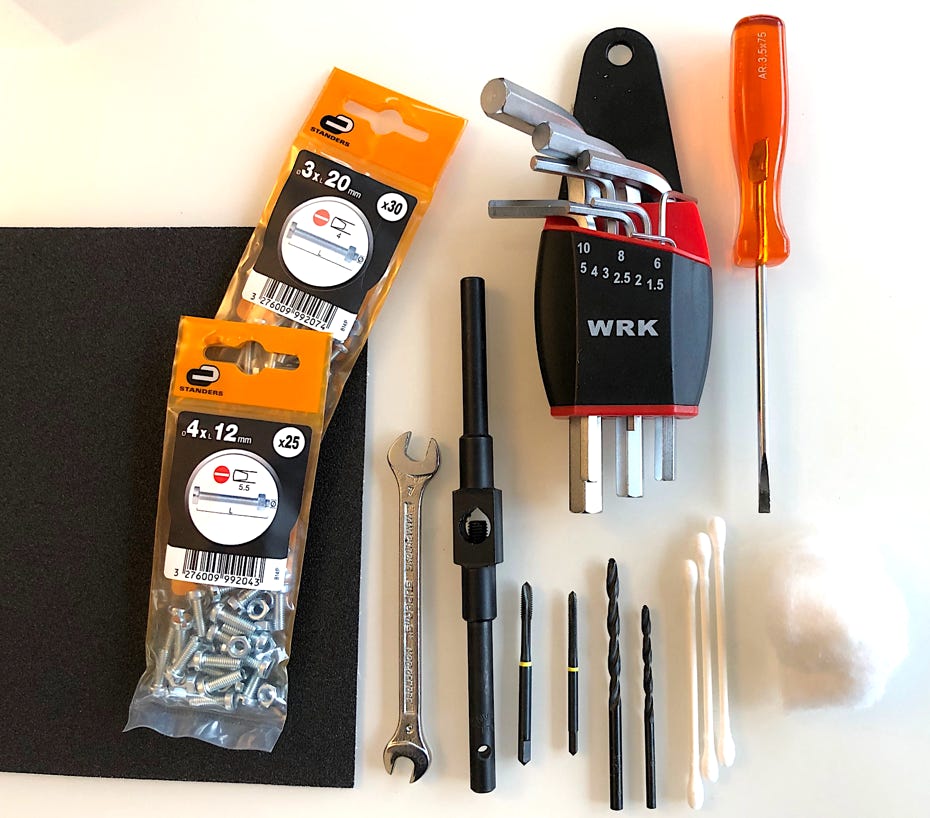
You'll need a few standard tools: a screwdriver, a set of Allen keys, a 7 mm open-end wrench, a left-hand screwdriver, an M3 tap, an M4 tap, two drills with diameters of 3 mm and 4 mm for deburring holes, medium emery cloth, essential for deburring parts made in 3D printing, absorbent cotton for cleaning the surface of a soiled lens (note that the surface of a diffraction grating cannot be cleaned; it cannot be rubbed, even very gently), M3 and M4 screws and bolts.
Many Sol'Ex parts require M3 and M4 threads. In most cases, rather than tapping directly into PETG, which is too fragile, we prefer to use inserts specially designed for 3D-printed parts. These inserts are heat-mounted.

Here's a list of the bolts you'll need to assemble Sol'Ex (ISO). Note that you'll need to purchase these bolts if you're printing the "historical" V1 version yourself. If you purchase both the V1 and V2 versions from Azur3DPrint, the screws and bolds are included in the kit you receive.
7 x M4 length 40mm
2 x M4 length 50 mm
4 x M4 length 30 mm
2 x M4 length 14 mm
7 x M4 length 12 mm
2 x M3 length 16 mm
3 x M3 length 8 mm
You'll also need M3 and M4 nuts and washers.
Assembly of the main box.


Mounting the grating on its support. Warning: a fingerprint on the engraved surface means it goes straight into the garbage can. You can't make up for an accident; it's irreversible. The only way to handle a grating is to hold it by its sides and rest it on the side opposite the engraving (the engraved side is easy to recognize, as it produces the colored iridescence on the surface). Very thin gloves can be used, but even then, if you touch the surface, it's damaged.


Pay close attention. This optical part consists of two parallel flat surfaces. One is the surface of the grating itself, which gives the irritations and is covered with a glossy coating, the other is an ungraved, transparent surface. Don't be mistaken about the mounting direction: the glossy side must always be positioned on the outside of the grating support (the light must not pass through the glass).

Mounting the collimator block and slit :


Mounting the camera lens :


To download the STL file for the support tool, click here (this support is included as standard in the V2 kit).


Collimator lens adjustment.
You can also download specific instructions in 3 PDF files: Solex_setting.zip
Slit and camera orientation adjustment.


Mounting the telescope interface.
Your Sol'Ex is now set up and ready to observe our star. But first, spend some time familiarizing yourself with the solar spectrum. On the table, simply aiming at the sky through a window, wander through the spectrum of the day's starlight.

Copyright (C) 2020-2023 Christian Buil
Web : www.astrosurf.com/buil