by Christian Buil
The Solar Explorer - October 25, 2023
by Christian Buil
The Solar Explorer - October 25, 2023
Theory

A little bit of instrumental theory ... Those who are most resistant to mathematics can skip this part, it will not prevent them from building and using Sol’Ex! For others, you will find here a justification for the design of this instrument, its size and the origin of its performance.
If Sol’EX is a spectroheliograph, it is above all a spectrograph, that is to say an instrument which records the decomposition in wavelength, or colors if one prefers, of light radiation. I have chosen the most classic and simplest optical arrangement for Sol’Ex, as I will show now.
The following figure shows the optical diagram:

The instrument entrance consists in narrow entry slit, 10 microns wide and 4.5 mm high, which is placed at the focal point of the telescope. Next comes a 80mm focal length lens collimator. This achromatic doublet has been specially optimized for Sol’Ex and uses a special high index glass. This objective makes the light rays emanating from a slit point parallel to each other. These then encounter a 2400 lines/mm diffraction grating of the holographic type, responsible for spectrally dispersing the light. A 125mm focal length lens, also manufactured especially for Sol'Ex, finally focuses all of the rays in the detector plane.
The average direction of the rays, before and after the grating, forms a "V" with an interior angle of 34°. This angle is called the "total" angle. It gives Sol’Ex its characteristic general shape.
One immediately notices the very strong angle of incidence of the rays coming from the collimator on the grating, approximately 72 when working around the H-alpha hydrogen line, at wavelength of 656 nm. This high incidence induces a strong vignetting of the rays collected by the telescope. The grating then being approximately the pupil of the system. According to the dispersion plane (the plane of the figure), the accepted beam opening is approximately f/10.6. In the perpendicular plane, and taking into account the field covered by the 4.5 mm high slit, the aperture of the system is approximately f/5.6. What is the significance of all this. Let's say you are using a scope that is 65mm in diameter and 420mm in focal length. The aperture ratio of this setup is therefore 420/65 = 6.5 approximately. In the first order, when this refractor is used with Sol'Ex, its effective aperture is therefore f/6.5 along the axis perpendicular to the plane of incidence (it is the physical aperture of the telescope that limits) and f /10.5 in the incidence plane (it is Sol'Ex which limits). If we could draw the effective outline of the useful area at the entrance of the refractor, we would have the shape of an ellipse and not a circle.
The sizing of Sol'Ex therefore causes a loss of flux, because your telescope lens is stopped (except when using a f /10 telescope approximatively). This situation is not critical for solar observation, because the available luminous flux is really abundant. The refractor and photographic lenses that can be used with Sol'Ex can be opened between f / 5.6 and f/9, without very noticeable effect on the images. However, if your instrument is basically very luminous, you can select various diaphragms in front of the objective and test for possible a improvement in image quality. I give examples in the "Observation" section. It also avoids concentrating excessive unnecessarily flux on a small point at the entrance to Sol’Ex. For example, if you want to use f/2.8 a photographic lens you should stop to f / 5.6, or even f / 7.5 (diffraction does not yet degrade performance in general with regard to specifications. by Sol'Ex).
If the strong impact on the grating causes a loss of flow, on the other hand it turns out to be very advantageous as regards the sharpness of the recorded spectrum. To understand this last point, we must notice the large difference in size of the light beam counted in the plane of incidence, before and after the grating (respectively D1 and D2):

This characteristic, specific to the use of a grating, is called an anamorphosis. Besides what happens to the size of the beams of rays, the anamorphosis also affects the size of the slit image on the detector. The image of the slit width is reduced by a factor D1 / D2, known as the anamorphosis factor. The size is, however, unchanged along the so-called spatial axis, perpendicular to the dispersion axis . To illustrate this situation, the following document shows the image of an optical fiber, temporarily replacing the Sol'Ex slit, with a round outline at the start, but the image of which ends up being oval:
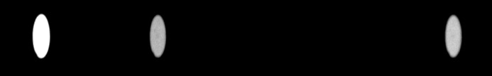
Appearance as a few monochromatic images of an optical fiber arranged at the entrance of Sol’Ex for wavelengths close to the H-alpha line.
Copyright (C) 2020-2023 Christian Buil
Web : www.astrosurf.com/buil
The reduction in the optical width of the slit caused by the anamorphosis has a significant net impact on the spectral resolving power of Sol'Ex, that is to say on the sharpness of the details of the spectrum that can be observed. In the case of Sol’Ex, this impact is very positive. He is responsible for the high performance achieved while Sol’Ex is a compact instrument.
Let's do some math. First the link between the total angle G (G = 34° for Sol’Ex) and the incidence angle alpha on the grating :
alpha = arcsin(k m lambda0 / (2 cos G/2) + G/2
where k, is the diffraction ordre (hère k = 1), m, the groove densité (ici m = 2400 lines/mm) and lambda0, the wavelength at the sensor center (here 0,6563x10⁻³ mm). We have also, G = alpha - beta, with beta, the diffraction angle.
For the observation of the H-alpha line (6563 A), the incidence angle of the rays on the grating is precisely alpha = 72.4° while the diffraction angle (after the grating) is beta = 38 , 4°. The anamorphosis factor is given by the formula:
A = cos (alpha) / cos (beta)
where A = cos (72.4 °) / cos (38.4 °) = 0.386. This means that the width of the entrance slit is reduced somewhat. (optically) at 0.386 x 10 microns = 3.86 microns. It is this result that causes a gain in spectral resolution. It should be added that towards the red line of hydrogen, but also a large part of the visible spectrum, the optics of Sol'Ex is almost limited by diffraction, that is to say it is very good ( since one does not simultaneously explore a very wide spectral domain).
The resolving power R is defined by the formula R = λ / Δλ, with λ the observation wavelength and Δλ the finest detail observed in the spectrum in units of wavelength. Note that R is a dimensionless number. The larger is R, the more small details are observed in the spectrum. We show that:
R = fc / w x (tan (alpha) + sin (beta) / cos (alpha))
as we have seen, alpha and beta, respectively the angle of incidence and diffraction on the grating. Furthermore, fc is the focal length of the collimator, here fc = 80 mm, and w is the physical width of the slit, here w = 10 microns = 0.010 mm. The phenomenon of anamorphosis is described by the term in parentheses of this formula, as well as the impact of the etching density of the grating. By doing the calculation around the H-alpha line, we find:
R = 80 / 0.010 x (tan (72.4 °) + sin (38.4 °) / cos (72.4)) = 41600
Considering the residual optical aberrations, we can consider Sol’Ex's resolving power to be close to R = 40,000, which is a remarkable performance for such a small instrument. We therefore theoretically solve in the red (but over a small width in wavelength) spectral details of Δλ = λ / R = 6563 / 40,000 = 0.16 A = 0.016 nm. This fineness makes the purity of the monochromatic images delivered by Sol'Ex higher than that obtained with interference filters, much more expensive.
Recall the fundamental formula of gratings, which relates the diffraction angle of diffraction to the incidence angle:
sin (alpha) + sin (beta) = m x λ
With m, the engraving density, here m = 2400 lines/mm and λ the wavelength, here λ = 0.6563e-3 mm. You can check that the alpha and beta values are correct.
Another important optical parameter is the spectral dispersion factor in the plane of the detector. It is a question of evaluating the small spectral range covered by a pixel of the detector. This parameter, denoted by r, if it is expressed in A/pixel (strictly speaking, it is a reciprocal dispersion), can be calculated with the formula:
r = 1e7 x p x cos (beta) / m / fo
with p the pixel size in millimeters and fo the focal length of the camera lens, here fo = 125 mm.
Suppose a CMOS camera using a Sony IMX178 CMOS sensor (ASI178MM camera from ZWO for example). The pixel size in this case is 2.4 microns, where p = 2.4 microns = 0.0024 mm and,
r = 1e7 x 0.0024 x cos (38.4 °) / 2400/125 = 0.063 A / pixel
It is important to compare the spectral resolution element Δλ calculated previously, that is 0.16 A and the sampling of the spectrum by the pixels of the detector, 0.063 A/pixel. It appears that we have 0.16 / 0.063 = 2.53 pixels per element of resolution, that is to say that we are above the Shannon (or Nyquist) limit which is two sample points per element of resolution. This is a good sizing for Sol’Ex. Note that if the ASI178MM camera is operated in 2x2 binning (equivalent to 4.8 micron pixels) the Shannon criterion is not respected, and therefore information is lost. For jobs that require high precision (Doppler measurements in particular), it is best to use a small pixel camera and work in 1x1 binning, if possible.
These sampling considerations fully justify the use of a fairly long focal length camera lens of fo = 125mm.
Another useful formula is the one that gives the spectral dispersion in A / mm, called the plate factor, denoted by the letter P:
P = 1e7 x cos (beta) / m / fo
With the values of our example we find,
P = 1e7 x cos (38.4) / 2400/125 = 26.1 A / mm
Now let's deal with the subject of Sun imagery itself. As a first approximation, along the spectral axis, the sharpness of the details observed on the surface of the Sun in arc second is given by the width of the slit at the focal point of the telescope using the formula:
Vx = 206264 x w / F
With w the physical width of the slit and F the focal length of the telescope. Suppose we are using a refractor with a focal length of 420 mm, in this case with w = 0.010 mm, we find:
Vx = 206264 x 0.010 mm / 420 = 4.9 arc seconds
In fact, the situation is more complicated, because you also have to take into account the size of the pixels and the anamorphosis, but the order of magnitude is good.
Along the spatial axis, the formula to use is,
Vy = 206264 x p x fc / fo / F
that is
Vy = 206264 x 0.0024 x 80/125/420 = 0.75 arc seconds
However, this result is very theoretical because it is geometric. In practice, taking into account optical aberrations, it is more necessary to count on a resolution of 3 seconds of arc on the solar disk. Likewise, it is quite common to work in 2x2 binning and in this case, the effective pixel size is p = 2.4 = 4.8 microns.
In the end, it is reasonable to assume that the spectral resolution is close to 3 arc seconds in this example. Atmospheric turbulence may well reduce this performance. On a hot day, seeing can easily exceed 3 arc seconds. If your seeing is better, the way to increase the angular resolution of the images is to increase the focal length of the refractor (I emphasize this point in the "Observation" section).
Finally, the question must be answered: can I capture the image of the entire sun disk in a single scan using a telescope with focal length F?
The apparent diameter of the Sun changes slightly depending on the season, but we consider here the diameter of 0.53 °, very representative. Since the length of the Sol’Ex slit is 4.5 mm, the desired limit focal length is given by the formula:
F_limite = 4.5 / tan (0.53 °) = 486 mm
However, it is prudent to take a margin of at least 10% to reasonably frame the disc over the length of the slit. So, focal length F of 440 to 450 mm is the reasonable maximum. Also, the edges of the slit are a little less sharp than the center, resulting in a potential little blurring at the poles of the disc if you are sweeping in right ascension. Ultimately, a focal length of around 420mm or less is ideal if you want to capture the entire disc with comfort. Of course the focal length can be much longer if this last point is not your priority, because you want to detail the solar surface as much as possible.