All the instructions required for the successful assembly of your Lhires III spectrograph can be found in the following pages. Although the various components are modular in nature and allow you easily to change the construction of the different sub-assemblies, the assembly sequence suggested below appears to be the most logical; it was the one that we thoroughly tested with the second prototype.
Before we get to grips with the details, here are a few general considerations for you to be aware of:
Okay! We have finished with the warnings and general considerations.... now its on to the details of construction!
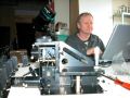
Use a large empty table to assemble your spectrograph, preferable in a quiet part of the house (with a mountain view!).
|
|
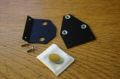
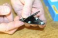
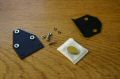
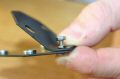
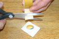
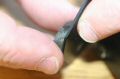
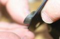
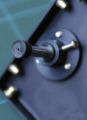
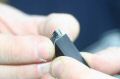
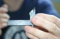
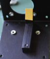
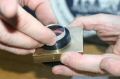
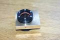
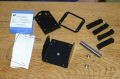
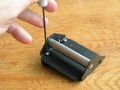
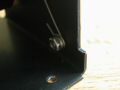
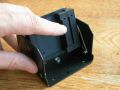
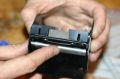
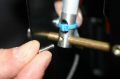
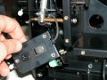
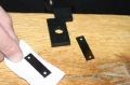
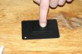
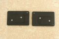
Assemble the Webcam mirror mount:
Materials: Webcam mirror supports 1 and 2, elliptical mirror, 3 M3 round-head screws, 2 M3 locking washers, 2 M3 nuts, 2cm of double-sided scotch tape.
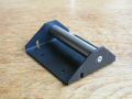
- Attach the two mirror supports together with 2 M3 bolts.
- Attach the mirror onto its support with the double-sided tape, ensuring that it is well centred and flush with the top of the support (refer to photo No. 8914).
- Avoid touching the reflective surface of the mirror with your fingers!
|
|
|
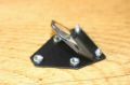
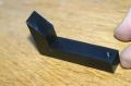
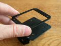
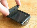
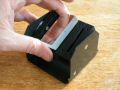
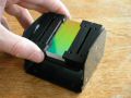
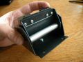
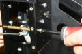
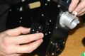
Mounting the mirror onto the spectrograph cover:
Materials: pre-assembled mirror on mount (see above), 4 M4 BTR screws with plastic caps.
- Attach three push screws and one pull screw.
- The mirror support should be located about 1 cm from the side of the cover.
|
|
|
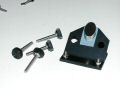
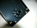
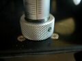
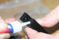
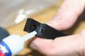
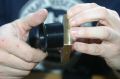
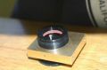
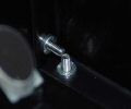
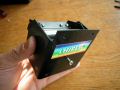
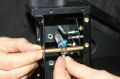
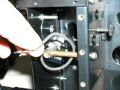
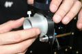
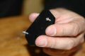
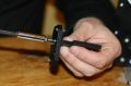
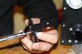
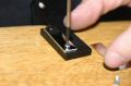
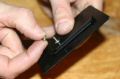
Attach the micrometer screw to its cover.
Materials: cover, micrometer thread collar with locking screw, micrometer and 4 M3 screws.
- Attach the micrometer collar onto the support with 3 M3 screws.
- Slide the micrometer through its collar and block it with the locking screw. The vernier scale graduations should be visible and the micrometer bar pushed as far as it will go in the collar.
- The vernier scale should be turned towards the short side.
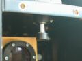
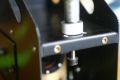
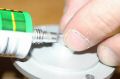
- Glue the tip of the micrometer
TIP: do a small hole to let air entered when you press the micrometer into the tip.
|
|
|
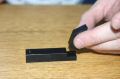
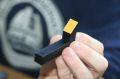
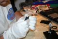
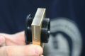
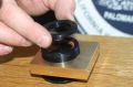
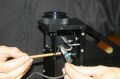
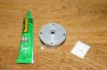
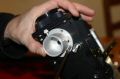
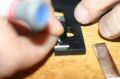
Mounting the main mirror:
Materials: Main mirror base, main mirror support, elliptical mirror, some Super Glue, 2 M4x 16 round-head screws, 2cm double-sided tape.
- Placing a single drop of glue onto the side of the support, attach the mirror base to its support (Care needed!)
- If needed, you can tighten gently the two parts with a screw whilst the adhesive dries (but avoid getting glue on the screw itself!!)
- Leave to dry for several minutes.
NOTE: you do not have to do the operations above as we did it before shipping kits...
- Attach the main mirror with double-sided tape and flush with the base (use provided gloves!)
- Attach the whole assembly to the main spectrograph body with 2 M4 x 16 screws.
TIP: one screw is longer than required; you can cut it and paint it in black...
|
|
|
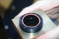
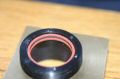
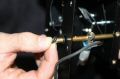
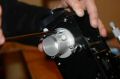
Assembly of the Collimator support:
Materials: Collimator lens tube, lens collar, two fibre O-rings 27x30mm, collimator doublet lens, locking ring, 6 M2 x 12 screws, nylon locking screw, 2 M4 x 10 screws.
- Attach the lens tube in the brass collar at about the mid point of its adjustment range.
- Add one of the fibre o-rings.
- Carefully place the lens in the tube.
NOTE: the lens goes one way to mnimize aberrations. Look at it and there should be one side which is flatter than the other; put that one so it's directed toward the 45° mirror.
- Add the second o-ring.
- Add the locking ring.
- Carefully tighten down the locking ring using 6 M2 x 6 screws, ensuring even screw pressure around the ring.
- Add the 2 nylon locking screws onto the side of the collar.
- Mount the complete assembly onto the reference L side of the spectrograph with 2 M4 x 10 screws, ensuring that you have chosen the correct side.
|
|
|
Stick the 4 rubber feet at the corners of the main body (L-Ref)
|
|
|
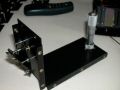
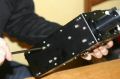
Attach the right hand side panel onto the main body (L-Ref)
Materials: L-Ref (already fitted with the main mirror assembly and the doublet), right hand side panel, 8 M3 screws.
TIP: two screws are touching each other. you can find a small screw for one or simply lime the end of the screws.
|
|
|
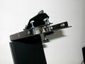
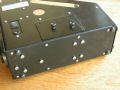
Fix the top cover onto the right hand panel:
Materials: previous assembly, top cover (including the Webcam mirror and the micrometer screw assembly), 6 M3 x 10 screws.
|
|
|
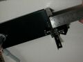
Assembly of the telescope interface:
Materials: Previous assembly, telescope coupling flange (depending on your instrument, this is either the 2 inch (50.8mm) adapter, or the fixing collar + threaded ring), 6 M4 x 16 countersunk screws, 8 M4 x 10 round-head screws.
- Attach the adapter of your choice to the coupling flange using the 6 M4 x 16 countersunk screws.
- Attach the flange to the left side of the spectrograph body with 6 of the 8 M4 x 10 round head screws (the last two screws will be screwed in later).
|
|
|
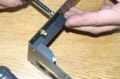
Assembly of the Grating Mount:
Materials: Grating support, grating back, grating frame, the 4 right-angled corners, grating axes (2 pieces, brass), pressure bar, 6 M3 x 10 screws, 8 M3 locking washers, 1 M4 screw, 1 M4 locking screw.
- Screw the retaining (pressure) bar on the grating support.
- Place the grating frame onto its support.
- Attach the two external right-angled brackets using the M3 x 10 screws and locking washers provided (use the one in aluminium for the external side; the one in plastic will hold the grating).
- Attach the spring to the support.
- Add the two brass axle pins onto the external brackets.
- Attach the looped ends of the spring around the axle pins.
- Carefully slide the above assembly into the support frame this can be a bit fiddly and requires you to open the frame slightly.
- The two pins should clip into the grating support holes used for this purpose. Check that the ends of the spring are fastened around the pins the axle pins should be flush with the support frame.
- Turn the grating mount so that the ends of the spring are near to the locating holes (M3 screw, flat washer, locking washer and nut!). Tighten with the supplied Allen key.
- Screw the ends of the spring into the grating support.
- Begin to assemble one of the two right-angled brackets used to hold the grating
NOTE: two are in plastic and two in aluminium; put the aluminium one outside and the plastic one to hold the grating
- Add a small square piece of tissue paper or kitchen towel on to the grating support in order to avoid fastening the grating too tightly.
- Insert the grating, making sure it is correctly orientated WARNING - the arrow should be uppermost! Again, avoid touching the delicate surface of the grating with your fingers This cannot be overemphasised!!
- Add the final right-angled bracket to fix the grating permanently in place, but DO NOT OVERTIGHTEN! The grating substrate is made of glass... too much strain here could fracture your valuable grating.
- Attach the grating stop screw (M4 x 10). Tighten it well down. This screw is used to block the grating mount but allows the retaining bar to pass in order to be able to observe the zero order.
|
|
|
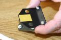
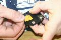
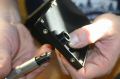
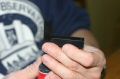
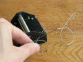
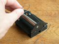
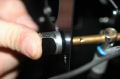
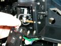
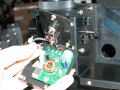
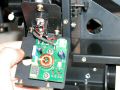
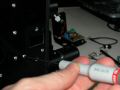
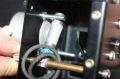
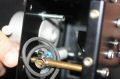
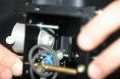
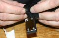
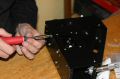
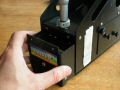
Assembly of the Neon lamp:
Materials: Neon lamp, coax cable, neon lamp holder, neon lamp axle pin lamp push-button, heat-shrink tubing, cable-tie.
- Reduce the length of one of the neon lamp wires to about 5mm and the other to about 10mm.
- Strip the coax cable by about 10mm.
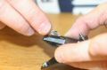
- Using a soldering iron, tin the wires of the lamp and the coax cable.
- Attach a small length of heat-shrink tubing (small diameter) onto one lamp wire.
- Solder the lamp wire to the coax cable.
- Slide the heat-shrink tubing over the solder joint and heat the tubing with the tip of the soldering iron to retract the tubing.
- Solder the other lamp wire (without heat-shrink tubing).
- Insert a short length of heat-shrink tubing (larger diameter) to completely cover the previous soldering and heat with the blade of the soldering iron to shrink the tube.
- Add a second length of tubing over about a 3cm length (for extra protection!)
NOTE: all the operations above have been done for you - you do not have to do them!!!
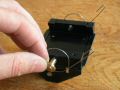
- Pass the wire through the lamp holder and slide the lamp to the correct position in front of the hole in the holder.
TIP: The heat shrink cable should exit the holder from a hole opposite of the window side.
- Attach the cable firmly with a cable-tie to prevent the lamp slipping in its holder.
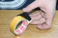
- Tape a small piece of matt tracing paper to the lamp window to diffuse the light.
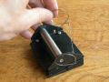
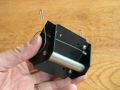
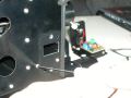
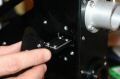
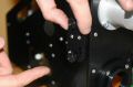
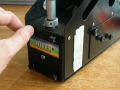
- Attach the above assembly to the spectrograph.
- Add one M4 x 10 screw + washer to inside of the spectrograph.
- Add two twisted o-rings to the axle pin from the outside of the spectrograph and attach the cap, tightening such that the lamp axle pin turns somewhat stiffly (see later when the body panels are to be closed).
- Insert one M3 x 10 screw to fix lamp holder along the rotation axis of the lamp.
- Pass the wire through the strain relief grommet.
- Plug the wires on the connector on the PCB (both ways work).
- Attach the Ne lamp switch support onto the spectrograph cover using 2 M3 x 10 screws.
NOTE: 12V connector is provided in the kit. When assembling, note that Ground is on the outside of the connector. Circuit is protected is go wrong - so you do not risk anything!
|
|
|
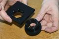
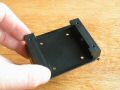
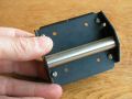
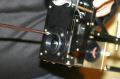
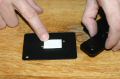
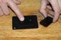
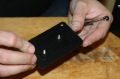
Assembly of the webcam holder
Materials: webcam mount, small lens, some universal glue
- Start putting the lens in its mount
- Put a smal glue point on the lens side
- Push the lens at maximum - use the gloves to prevent any mark
- Install the mount on the Lhires III chassis
- Put two screws M4x10 (one towards the neon axis, and the other at the opposite)
- Put two screws M4x25 (they will block the neon lamp on both sides)
|
|
|
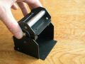
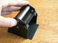
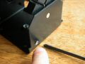
Assembly of the CCD camera holder
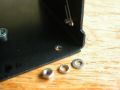
Material: Camera mount, 4 screws M4*12, V-head
- Tighten the holder on the Lhires III chassis
NOTE: to mount a photographic camera, you will need a T-ring. First time you mount it, adjust the T-ring (there are usually small screws on the side) to rotate the camera and align it horizontally. You should have to do it only once normally.
|
|
|
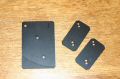
Assembly, tuning of the slit
Material: Slit support (1&2), 4 screws M3*10, 2 screws M4*12 with knobs, 2 half-slit, 4 screws M2*6
- Put the knobs on the BTR screws
- Put 2 screws M3*10 in the support (they will act as guide)
- Assemble support 1 & 2 with screws M3*10
- Put the slit with 2 screws M2*6
- Refer to the slit tuning process (adjusting procedure,- can be done later)
- Put the slit holder on the chassis
NOTE: you should have received a special paper within the kit that allow you to rectify the slit if needed.
|
|
|
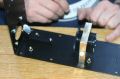
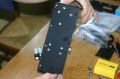
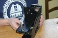
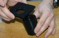
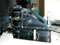
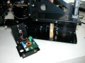
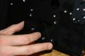
Closing of the chassis and doors
(Note that global geometry of the chassis can be modified when unassembled - tuning must be
at least checked when you remove one of the main parts)
Materials: 6 screws M4*10, 17 screws M3*10, 2 doors, and 4 door brackets
- Put the left side on the chassis, and tighten all screws (2xM4*10, and M3*10)
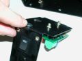
- Put 2 door brackets on each door, with a gap between each. Tighten the parts together
with screws M3*10 + knobs - you should a bold on screws before mounting, to put some gap
between doors and screw head (this will help to catch the doors).
- Put the doors on the chassis
- TIP: look at the picture with the two doors to mount them correctly.
- TIP: use screw with button - it will be easier to manipulate them!
|
|
|
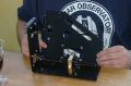
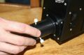
Final assembly
- Open the micrometer to the max (around 25mm)
- Slide the grating mount, and tighten it with 4 screws M3 (with knob)
- Add 4 screws M4*10 on the bottom face of the Lhires III (these locations are made
to put a "future" additionnal part to attache the Lhires III - feel free ti use them !)
- Mount the eyepiece holder (or a CCD older, depending on your program)
- At this stage, you should check that neon lamp can turn when you move
the button. If the neon cannot stay in place, tighten the button when pusshing on it.
|
|
|
|
)
)
)
)
)
)
)
)
)
)
)
)
)
)
)
)
)
)
)
)
)
)
)
)
)
)
)
)
)
)
)
)
)
)
)
)
)
)
)
)
)
)
)
)
)
)
)
)
)
)
)
)
)
)
)
)
)
)
)
)
)
)
)
)
)
)
)
)
)
)
)
)
)
)
)
)
)
)
)
)
)
)
)
)
)
)
)
)
)
)
)
)
)
)
)
)
)
)
)
)
)
)
)
)
)
)
)
)
)
)
)
)
)
)
)
)
)
)
)
)
)
)
)
)
)
)
)
)
)
)
)
)
)
)
)
)
)
)
)
)
)
)
)
)
)
)
)
)
)
)
)
)
)
)
)
)
)
)
)
)
)
)
)
)
)
)
)
)
)
)
)
)
)
)
)
)
)
)
)
)
)
)
)
)
)
)
)
)
)
)
)
)
)
)
)
)
)
)
)
)
)
)
)
)
)
)
)
)