)
)
)
Slit width adjusting
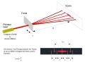
The slit width is a key point of the instrument. It determines the resolution of your spectra.
Nominal width is 25 µm. If it's bigger, you'll decrease the resolution. If it's smaller you'll lose some
flux. Then you should tune this parameter as precisely as possible. Measuring a width of 25 µm is not obvious - you can make it just by looking at light through the slit with some experience (;>), but we''ve got a more determinist method (thanks to Benoit Minster): Optics rules say that if you send a laser toward the slit, that makes a diffraction pattern, with a proportionnal size to the slit width. Thanks to the Nature... Do it in the dark to better see the patterns!
You'll need some time to get the right tuning, but at the end of the day, you'll love that (this is to be shown to the kids !)
Note that the slit tuning is made manually: you've to untighten the screws, move the half-slit smoothly (very smoothly...), and tighten back.
You will be also careful to the slit parallelism - this is very easy to control visually, by looking at the daylight through the slit !
)
)
)
)
)
)
)
)
)
)
)
)
)
)
Visualize the solar spectrum... with your eye !
From now, you'll start to see the solar spectrm. This important, not only because it's beautyful, but also because you'll get the exact position (angle) of the grating for different typical wavelengths.
- Put the eye-piece mount and an eyepiece on the spectro.
- Adjust the micrmeter to about 20mm.
- Adjust the main mirror to the middle position (screws M4, on the bottom face of the Lhires III)
- Open a side door, and put the collimation lens holder at medium position.
- Choose a sunny day... or find a powerful light (but for sure, the sunis much better !)
- Point the spectro towards the sun (the slit must receive direct light from sun).
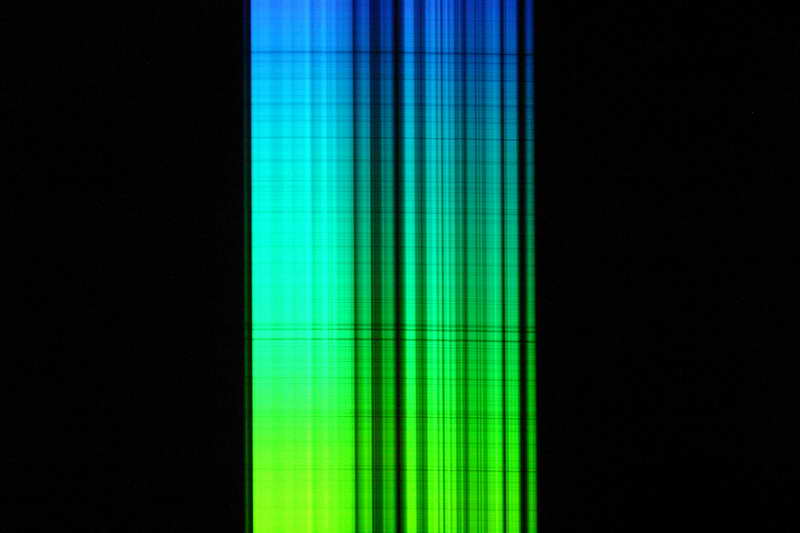
- Then you should be able to see your first high resolution spectrum of the sun ! This is a large band, whose color depends ont the region you'r looking at.
- *** IMPORTANTE NOTE *** There is no danger to look at sun this way (with no telescope). The slit is so small that only a few part of the sun light goes through the instrument, and it is very dispersed.
- At this stage, you can focus the collimation lens. Then you'll see a lot of absorbing lines across the spectrum.
- It's possible that you also see deep black lines in the direction of the spectrum dispersion. This very probably the effect of dust in the slit, or small defects on the slit edge.
- Move the grating angle (by turning the micrometer), to explore the full solar spectrum. You'll should recognize major lines such as Ha (6563 A - in my case micrometer position is 21,64mm), sodium doublet (in may case, 19,38mm), and so on. The full spectrum goes roughly from 13,5mm (deep purple) to 23,5mm (dark red) - which makes about 20 turns, and hundreds of absorption lines ! How great is spectro, isnt'it ?
- Then, to complete this color trip, look for the zero order (around position 0 of the micrometer). You'll see a single line very bright - it's better to point slightly beside the sun. In this position, the grating works as a mirror, and what you see is the image onf the slit. Record precisely the micrometer position for each recognized wavelength.
)
Note: If the weather is bad (:<), you also can do all this step with the neon lamp. In this case, prevent any parasit from daylight.
Here is an exemple of neon spectrum...
NOTE: lines are curved and it's normal. This is because we work in 3D, and not in a 2D plan. We are working slightly off-axis, thus a line deformation.
)
)
)
)
)
Adjusting guiding mirror
The guiding mirror is made to redirect skyfield to the guding camera. This adjustment have no effect on the spectrum quality, but it facilitates the guiding (even autoguiding) of the telescop during the acquisition. The adjutment can be made in two steps:
1) In a first time, it can be adjusted roughly, with the same kind of method used to tune the collimation of a telescope: Just put the Lhires III on a table, and look at it from the top (your eye takes place of the telescope). When the position is OK, you should see the guding camera lens picture well centered in the spectro. You can adjust the position of themirror by turning the 4 screws (1 pushing , and 3 pulling) accessible from ouside. At this stage, you must check that the neon holder can freely move without interferring with the mirror (you can check it easily by looking into the spectro from the some position).
)
)
)
)
)
)
)
)
2) A fine tuning can be made by materializing the slit center, and checking that this part of the slit is sen in the center of the guiding camera field. Note: materializing the slit center wil lbe reused in next steps.
- Unmount the slit holder
- Put 2 paper small sheets, spaced by 2-3mm. Use adhesive tape to stcik them (on the holder, not directly on the polished faces of slit !). Ensure that the 2-3mm gap is well positionned in the mechanical center of the slit. This part shows the area where the star beam will have to go.
- Mount back the slit holder.

)
)
)
)
)
- Mount the spectro on the telescope (and point it to the sky - not to the sun, with no motion)
- Install the guiding camera (webcam, video camera...), and visualize the image (monitor, PC...)
- Adjust manually the focus of the camera in order to see the slit acurately.
- Fine tune the mirror, in order to put the slit center image in the center of the picture.
- The mirror adjustment is done. You can remove the papers, but you can also keep them, for next steps !
)
)
)
)
)
)
)
)
)
)
Adjusting main mirror
This adjustment is important for the quality of the specra produced by your Lhires III. you will turn the main mirror so that the light beam dispersed by the grating pass right beside the mirror. If the angle is too small, mirror will block some light and there will be a vignetting effect; if the angle is too large, the beam will be too far from the optical axis and spectra will be impacted by the doublet chromatism.
Ce réglage est important pour la qualité des spectres qui seront produits par linstrument. Il consiste à tourner le miroir principal pour que le faisceau dispersé par le réseau passe juste à côté du miroir. Si langle est trop petit, alors on sexpose à un vignettage (perte de flux). Sil est trop grand, le faisceau séloignera trop de laxe optique, au détriment de la qualité (le doublet collimateur utilisé dans le Lhires III est dautant moins affecté par des problèmes de chromatisme que lon travaille à proximité de laxe optique).
There are two steps: a simple adjusting with naked eye and finetuning with your acquisition camera.
- simple adjusting
- Materialize the center of the slit (cf previous paragraph)
- Put an eye piece on the spectrographe (for exemple, a 25mm one)
- Note: you can perform this on the telescope pointing toward the sy (but not the Sun directly) or without a telescope and pointing the spectrograph alone toward the Sun.
- Position the grating angle so that you can vizualize the zero order of the spectra (you should have noted this position during your first adjustments). It should be around 0mm on the micrometer.
- While looking through the eyepiece, adjust the mirror angle (screw at the bottom of the chassis) so the center of the slit is at the center of the field of view.
- Finetuning
- Replace the eyepiece with your CCD camera
- run continuous exposures (around 1sec?) eventually in binning 2x2 or 3x3.
- Position the slit to the center of your image: by adjusting
- doublet focus if you do not see the slit (changing from eyepiece to camera requires some adjustment)
- grating angle
- main mirror angle
- Playing with those three adjustments, you should quickly find the ideal positions.
- Eventually, try to put the slit closer to one edge to avoid vignetting. Shift the mirror screw slightly toward the slit trappe so the slit image is at 1/3rd of the CCDimage. This way, you optimize the position and reduce risk of vignetting. This is not mandatory but good to do...
Note where your spectrum is on the CCD - this is where you will have to find your star.
)
)
)
)
Adjusting grating position
Before taking a stellar spectra, you still have one adjustment to perform. It does require patience. It's not absolutely mandatory but it will help you afterward. You will also have to do it when changing grating if you only have one support.
Goal is to put grating line parallel to the rotation axis of the grating support. when they are not, lines will follow a conic curve instead of a cylindric one. Projected image on the CCD will shift when changing the wavelength and move eventually out of the CCD camera. Ideally, your should have the zero order and the full spectra within your CCD, and even within a small portion of the chip! We will then check that zero order (close to 0mm) and red portion of the spectra (around 25mm) will be at the same position.
To correct the position, you have to do the following:
- Dismantle the grating support
- Adjust the grating as parallel as possible with the support edge (or rotate depending on your measurement of the shift)
- Re-mount the grating support and control it again.
- After few iterations and some practice, you will obtain a perfect tuning.
- Eventually, you can now readjust main mirror to put the slit centered on your capteur