Contrast factor of the F-P etalon and blocking filter assembly
3) Daystar filter modelling and additional results
4) Air-spaced F-P etalon theoritical performances and comparison with mica-spaced etalons
5) Analysis of the PST modification (air-spaced F-P etalon) and comparison between collimated and telecentric mounts
6) Contrast factor of the F-P etalon and blocking filter assembly
7) Contrast factor of the F-P etalon : test of various stacking schemes
8) Fabry-Perot math and bibliography
Test 1 : Daystar PE 0.6A versus Daystar PE 0.6 A + Omega 4.5 A
Test 2 : PE 0.6A, PE 0.6A + TO 0.9A, Ion 0.3A , PE 0.6A + Ion 0.3A
Test 3 : PE 0.6A, PE 0.6A + 0.9A etalon, Ion 0.3A
The 0.9A etalon has a good transmission :
The exposure time with the PE 0.6 A + 0.9A etalon is 3.3 x the exposure time with the PE 0.6A. By comparison, the exposure time with the Ion 0.3A is 6.7 x the exposure time with the PE 0.6A.
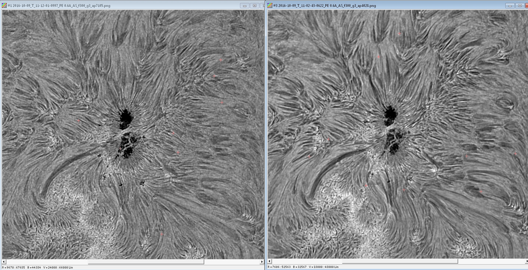
Daystar PE 0.6A (left) compared to Daystar PE 0.6A + 0.9A etalon (right) :
The benefit of the 0.9A etalon is obvious. The granulation (from the photosphere) is much less visible with the 0.6A + 0.9A stack.
Daystar Ion 0.3A (left) compared to Daystar PE 0.6A + 0.9A etalon (right) :
The CWL is probably not the same in both images.
