Analysis of Ha Fabry-Perot etalons
3) Daystar filter modelling and additional results
4) Air-spaced F-P etalon theoritical performances and comparison with mica-spaced etalons
5) Analysis of the PST modification (air-spaced F-P etalon) and comparison between collimated and telecentric mounts
6) Contrast factor of the F-P etalon and blocking filter assembly
7) Contrast factor of the F-P etalon : test of various stacking schemes
Reference comparison images for the qualitative evaluation of the FWHM of Ha etalons
8) Fabry-Perot math and bibliography

This is the case with an etalon placed in front of the objective of a refractor or in an internal position after a collimating lens.
Let's consider a collimated beam (i.e. a set of parallel beams of light) incident on the F-P at an angle from normal incidence :
1) Center Wavelength Shift with the incident angle :
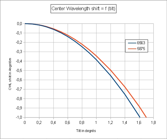
In these conditions, the Center WaveLength (CWL) of the F-P filter is shifted to the blue when the incident angle increases. For small incidence angles we have (1) :
The blue shift with increasing incident angle (or field angle) is the explanation of the formation of a sweet spot in collimated mounts: only the center of the field of view is centered on Ha (more on sweet spot formation here).
Here are simulation of the CWL drift for a mica-spaced F-P etalon such as Daystar filters:
The calculated curve matches perfectly the curve given in Daystar white book for Helium D3 line (5873 A).
The blue shift of the center wavelength with the tilt is not a big deal for thermo-regulated filters, since the CWL can be tuned by increasing the temperature of the filter oven (increasing the temperature of the filter shifts the CWL to the red).
2) FWHM as a function of the tilt :
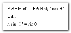
In a collimated beam, the change of FWHM with the incident angle is completely negligable (2) :
A a numerical example, a FWHM 0.6000 A filter would become a FWHM 0.6001 when tilted by 1°. Not a big deal ...
In a telecentric system, the field angle is equal to 0. In other words, the axis of the all incident cones of light (called chief rays) are perpendicular to the F-P etalon (figure taken from Zeemax help) :

See also a full drawing of a telecentric system here : http://www.pbase.com/p_zetner/image/151958178
More on telecentric mount here.
This means that, in a telecentric beam, the CWL shift and FWHM broadening is uniform all over the field of view.
Impact of the f-ratio on the transmission profile of an etalon in telecentric mount
The amplitudes of the CWL shift, FWHM broadening, and reduction of transmission peak depend on the f-ratio as shown in the following figure for a 0.7A mica-spaced etalon:
NB : this figure is calculated by direct integration of the Lorentzian transmission of a mica-spaced F-P etalon over the pupil of the telescope, considering a telecentric beam, a FSR of 27 A and an index n = 1.56.
CWL shift with f-ratio
For a mica-spaced etalon (FSR = 27 A, index n = 1.56):
The blueshift of the CWLwith f-ratio in telecentric systems is not a big deal as it is uniform all over the field of view. It can be conpensated by an increase of the temperature of the Fabry-Perot etalon. Still, it should be kept in mind when using the same etalon on telescopes with different f-ratio.
FWHM versus focal ratio
The following figures are calculated by integration of the Lorentzian transmission function of mica-spaced F-P etalon over the pupil of the telescope, considering a telecentric beam, and for a FSR of 27 A and an index n = 1.56.

Obviously, the broadening of the FWHM for a given f-ratio is more detrimental to narrower filters. Accordingly, it is recommended to use a f-ratio larger than about 28 when using a mica-spaced etalon in telecentric beam.
Link to (FWHM, CWL, selectivity) = f (f-ratio) for mica-spaced etalons in text file
Link to (FWHM, CWL, selectivity) = f (f-ratio) for air-spaced etalons in text file
Comparison with information provided in DayStar white bookDaystar white book gives a very different curve for a 0.5 A mica-spaced Ha filter (see the blue curve at left herafter). This curve is very doubtfull and definitely not the result of a measurement since a 0.5 A mica-spaced etalon in collimated beam has an effective FWHM of 0.6 A in a telecentric f/30 beam (instead of 0.5 A indicated on the figure).
This is not a calculation either since the only way to get close to this curve, is to assume an index of 1.96 for the cavity (red curve at right), which is far away from the actual index of mica.

Some notes on the index of mica:
Mica (muscovite) being birefringent, the refractive index depends on the polarisation of the light. The refractive index ranges between 1.59 to 1.64 (na = 1.55 to 1.58, nb = 1.58 to 1.61).
Measurements done by the author with a spectrometer on several mica-spaced etalons are in the range of 1.56.
Measurements done at Meudon Observatory (solar tower spectrograph, see ref W9 and WB) on a 0.35 A DayStar filter and a 0.3 A DayStar filter were consistent with n = 1.6173 and 1.62.
Telecentric lens system and tilted F-P etalon :
In real life, the F-P etalon might be tilted for at least two reasons:
- angular slop of poor focusing mechanism. Daystar says that most of Crayford focusers have a small 0.5° angular slop(see http://www.daystarfilters.com/Quark/QuarkUniformity.shtml) ;
- F-P etalon intentionally tilted (typical + or -1°) in order to quickly change the CWL (typicaly + or - 0.5 A). Indeed, tuning the CWL by increasing of decreasing the temperature of the F-P takes 10 mn or so.
Strictly speaking, even if we use a telecentric mount, we are no more telecentric in these conditions since we have a constant field angle all over the field. This field angle shifts the CWL (we have seen this is not an issue) and broadens the FWHM uniformly over the field (which reduces the contrast).
FWHM in function of f-ratio and filter tilt angle for mica-spaced F-P etalons:
In the following simulations (calcuation by integration of the Lorentzian transmission profile over the pupil of the telescope), we consider that :
- the optical axis of the telecentric system is identical to the optical axis of the telescope,
- the etalon is tilted by a given angle with respect to the optical axis of the telecentric system.


A pratical maximum allowance of 0.25° tilt can be considered if we want to keep the FWHM broadening to lower than 0.1 A.
Noteworthy, the transmission profile looses its symetry when the etalon is tilted:
Another source of discrepancy between "best case" and "real life", is that telecentric lens systems are designed for an objective (or a mirror) of a given focal length. In other words, if we use a telecentric system optimised for a refractor of 800 mm FL on a refractor of 2000 mm FL, we get a degradation of the etalon performance. This is because the field angle is no longer equal to zero all over the field of view as in a true telecentric system, but varies according to the linear distance from the optical axis. The following formulae are from Gene A. Baraff (ref W1) (5) :

Given the formulae (3) and (5), we can calculate the CWL shift and FWHM broadening resulting from the use of a non-optimized telecentric system .
For illustration, we will take the example of the Baader TZ2 (X2 magnification factor) and TZ4 (X2 magnification factor) telecentric systems, both optimized for 800 mm focal length, and we will check out their performances on three refractors of 440 mm, 1100 mm and 2050 mm FL :
- (a) A 55 mm F/8 refractor of 440 mm focal length. The effective focal ratio with the TZ4 is 8 x 4 = 32.0.
- (b) A 150 mm F/7.3 refractor of 1100 mm focal length. The effective focal ratio with the TZ4 is 7.3 x 4 = 29.2.
- (c) A 230 mm F/9 refractor of 2052 mm focal length. The effective focal ratio with the TZ4 is 9 x 4 = 36.0.
All refractors are stopped down to 50% aperture when used with the TZ2 in order to keep the same effective F/D ratio as with the TZ4.
CWL shift (mica-spaced F-P etalon) :
For the TZ2, the CWL shift from center to 16 mm from the optical axis is very small (lower than 0.1 A).
For the TZ4, the CWL shift is not noticable (lower 0.02 A).
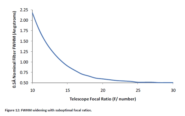
FWHM broadening with the TZ 2 (mica-spaced F-P etalon) :
The 440 mm FL refractor is the one suffering the most from the use of a non-optimized telecentric system, with a broadening of the FWHM from center to 16 mm from center of about 0.15 A.
The FWHM broadening can be considered as negligeable or very small on the 1100 mm and 2050 mm FL refractors (resp. 0.05 A and 0.08 A)
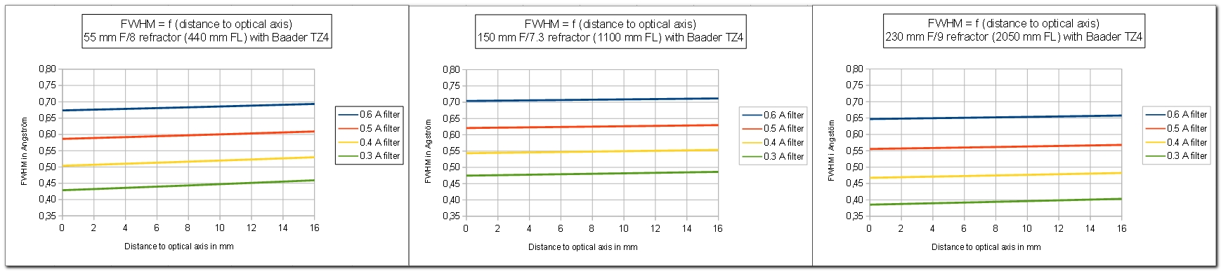
FWHM broadening with the TZ 4 (mica-spaced F-P etalon) :
The greater magnification factor of the TZ4 (X4 instead of X2) results in a lower sensitivity to the focal length of the refractor. Any focal lengths over 440 mm will give excellent results.
Conclusions on the use of non-optimized telecentric systems (mica-spaced F-P etalon) :
Even if they are optimized for a specific focal length, telecentric systems can be used with some flexibility regarding focal length. Telecentric lens systems with higher magnification factor have more flexibility on the focal length.
Degradation of performance comes first for short focal lengths.
In order to benefit from the full performance of mica-spaced F-P etalons, the following requirements are to be met :
a) Use of a true telecentric lens system (such as Baader TZ or Beloptik). So called "telecentric Barlow lenses" are not trully telecentric and will give inferior quality. The good news is that true telecentric lens systems give good performance, even when used on a telescope with a focal length different to their designed focal length (within some limits ...)
b) Check out the the squareness of the F-P etalons to the optical axis. In other words, there should be no compromise on the mechanical set-up. As a rule of thumb the maximum allowance for the tilt is 0.25°.
It is a very easy to check out the squareness of the F-P etalon by auto-collimation :
- Place yourself at a few meters from the objective of your refractor.
- You should see : the cercle of the objective, the cercle of the etalon, and ... the reflection of your eye on the etalon.
- The reflection of your eye should be centered on the image of the etalon and on the objective.
Otherwise you should arrange the mechanical set-up.
c) The longer the f-ratio the better the performances are. f/30 seems to be a good starting point.