 |
 |
|
Last Modified:
email dave@allmon.com |
|
 |
 |
 |
 |
 |
 |
 |
|
A workaround...
|
|
|
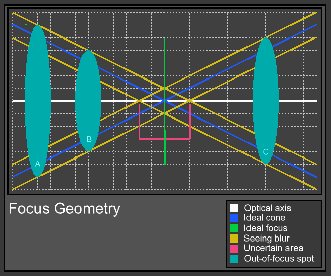
The graph above shows an area near the focus of an idealized telescope. Under good seeing conditions this idealized (and well collimated) scope will produce a perfect spot at the focus. This will be found at the intersection of the blue and green lines. Best focus is easily located by using only the FWHM reading of a star.
Under less ideal conditions the cone will change size and shape. The new size and shape will be determined by the quality of seeing, and for the purpose of this discussion will occupy the area between the yellow lines. The new focal plane will at any time be somewhere between the red lines, but on average will remain at the ideal focal plane.
Attempting to find the ideal focal plane by measuring the FWHM in the near vicinity, can be frustrating. The FWHM will vary between the ideal spot size and, in the example, four pixels. The FWHM will average out to be about the same anywhere in this area of uncertainty.
|
|
|
|
I have been thinking of possible ways to auto focus. The FWHM at focus seems like a good way to do it, but because of this scintillation caused by seeing, it is unlikely that a reliable reading can be had. A possible solution is to factor the seeing in, by making a pair of exposures at different points inside of focus that have a duration great enough to include the average seeing blur. In the graph these could be at the spot locations `Aī and `Bī. Exposing long enough to get the largest diameter of the cone, and then determining the slope of the cone, one could calculate the location of the plane on which the cone will converge. The problem with this method is that the cone will never produce a spot. The calculation will instead return the location of the righthand edge of the area of uncertainty (assuming the light enters from the left).
Knowing the angle of convergence, and that it is the same inside and outside of focus, one could then find the location of the lefthand edge of the area of uncertainty by taking only one reading outside of focus (as at `Cī), and applying the known slope (in reverse) to it. With these two points located, and again knowing that the angle is the same both inside and outside of focus, we can deduce that the point of best focus will be exactly equidistant from both. Assuming the DRO reads lower to the left and higher to the right, best focus will be
[Left + (Right - Left) / 2]
|
|
|
A star is selected which is bright enough to give a visible out-of-focus donut, but which will not be saturated during a 5 second exposure. The approximate focus is found. Remember the count, and zero the DRO (yes, DRO - Calculations require numbers).
The focuser is run either inside or outside of focus until a donut of approximately 10 to 15 pixels diameter is created. The FWHM of the donut is calculated using the capture program. The DRO is zeroed. The DRO position (zero) and the diameter of the donut are entered into a program. This donut reflects the size of the outer yellow lines in the diagram above, somewhere far outside the area of uncertainty.
The focuser is then run toward focus, but only about half of the way to focus. The count we remembered above is used to keep us from going too far. The distance is not critical, but we want to be measurably away from focus, and far outside the uncertainty. Another image is made. The position of the DRO and the FWHM are entered in the second line of the program. The program now has enough information to calculate the angle of convergence of the outer yellow line. If seeing were perfect, this would be enough to find the best focus, but the reason weīre doing this is because seeing isnīt perfect. Calculating the point where the lines intersect would give us the righthand edge of the area of uncertainty.
We need one more reading, this time on the other side of focus. Again, remembering our original focus position, we want to run out past it enough to get past the uncertainty, and make a donut around the size of the first one, although it isnīt critical at all. Again the readings are entered into the program.
Now the program has enough information to calculate the convergence points from both sides of focus (all of the yellow lines above). The convergence points of the two cones will be on opposite sides of focus, and best focus will be exactly halfway between those two convergence points. The area of uncertainty will encompass both of these points.
It is important to rack the focus back on the first side of focus and then turn around and come back at the calculated focaus if your focuser has any backlash at all.
I have tested the program, and I canīt find a focus better than the one it calculates. I have only tested it on my 10" LX-200 using the 0.33 reducer and a Genesis camera.
|
|
|
|
|
|
|
FocusCalc.zip |
(138,981 bytes) |
|
04/03/01 |
Original |
|
04/04/01 |
Modified to accept negative numbers in the position column, so that zeroing the DRO is not required. |
|
|
|
|
|
|
|
|
|


