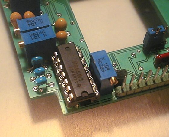
The U3 integrated circuit is at its place. Check that the slot on
the case is well oriented.
A voltmeter will be your main testing tool for Audine boards. Of course, you will also need a +/-15V source, and then a computer and a linking cable between the PC and the Audine boards.
To begin, you will set the integrated circuit U3 (quad amplifier LM348)
in its socket onto the inferior board. Be careful : make this mounting
only if the electrical tests of the inferior
board were successfully realized. Furthermore, never
plug an integrated circuit when the camera is under tension.
To put the integrated circuit in its tulip socket, bend with a flat
clamp simultaneously all the pins of each circuit row to make them parallel.
The circuit should then easily be plugged, but do not hesitate to force
slightly to ensure the connections.
The U3 integrated circuit is at its place. Check that the slot on
the case is well oriented.
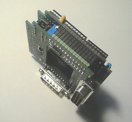
Dont set any integrated circuit in the sockets of the superior board for the moment.
Link the two boards thanks to their two rows of connectors. You cant make any mistake because the boards are only superimposable in the right way. Check that all the male pins are plugged in the corresponding female ones.
Put under tension the boards with a 3 strands cable connected with a +/-15V source. To connect the source wires, read again what is written for the test of the inferior board.
All the following tests must be made with the numerical voltmeter. The best is to take the ground on the pin number 14 of the CCD (the one you had forced to the ground thanks to a strap !).
The pin 14 of the CCD is linked to the ground. It will be your reference
during the tests of the board with the voltmeter.
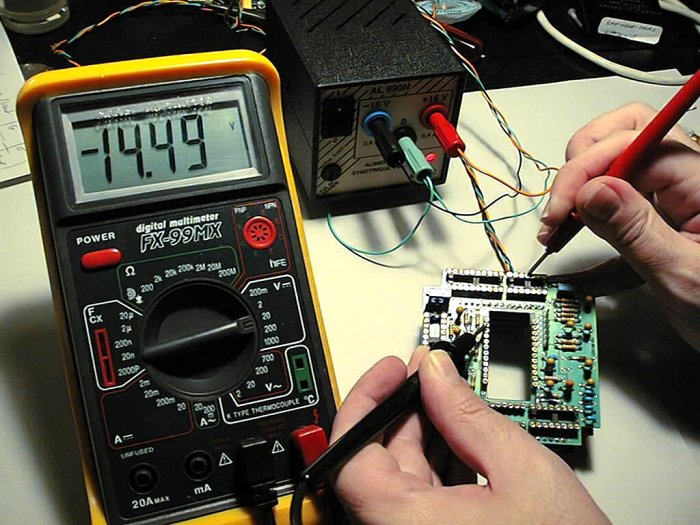
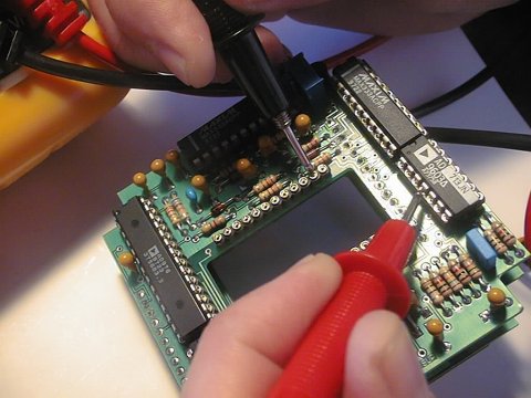
On this photo you can see the measurement of the tension of the
circuit U6 (AD713) pin 11, with the voltmeter positive probe. The negative
probe is connected to the ground of the circuit (pin 14 of the CCD).
These are the voltages to check :
|
|
|
|
| U4 | 16 | +15V |
| U4 | 5 | -15V |
| U5 | 16 | +15V |
| U5 | 5 | -15V |
| U6 | 4 | +15V |
| U6 | 11 | -15V |
| U7 | 28 | +5V |
| U7 | 27 | +5V |
| U8 | 16 | +5V |
The values that you will measure can have a difference of 5 to 10% compared with the values in the array because of the dispersion of the components characteristics. But this is not critical.
You have just tested all the integrated circuits power supplies (except CCD). Now, you must connect the PC/camera linking cable previously made to check the good reception of the command signals emitted by the PC. Connect the female side with the male 25 points connector of the camera, and the other side with the printer port of your PC.
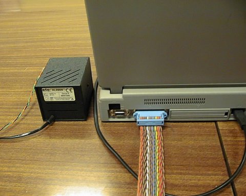
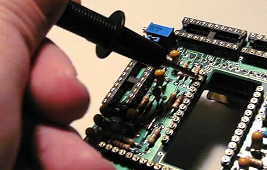
The ribbon cable is connected with the PC printer port, here
the back of a portable computer. On the left, the small ELC +/-15V power
supply.
The tests with the computer need the PISCO software to be installed.
Start the PISCO program. Right click the image zone (in dark blue) to see a popup menu. Execute the Console command.
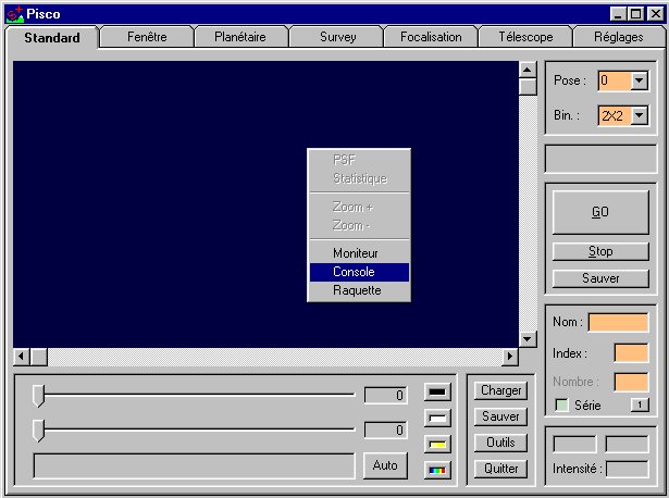
NOTA : the whole of the commands described in this section can also be executed from the Console mode of the IRIS software.
Connect the two Audine assembled boards to the PC, with the 25 points nappe cable. Theres no problem if the PC is on. Switch the camera power supply on, having checked the integrity of the connections.
Come back to PISCO. Enter the SET0 command and valid it by pressing the Enter key on the keyboard.
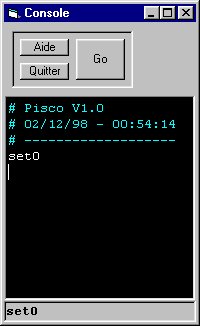
OUT 888,0
This means that the printer port data register is set to 0, where 888 is the decimal address (or 378 in hexadecimal) of the parallel port for most of the PC.
CAUTION : in some rare cases, the printer port address isnt 888. To know it, click here. Consult also the users guide of PISCO software to parameter it correctly.
Remember that the CMS interface circuits 74HCT14 set on the inferior board reverse the logical state of the signal applied to their inputs. So, if you put all the command bits at 0 with the software, the corresponding logical signals in the camera are at a high level.
After having switched the camera on, and executed the SET0
instruction, measure with the voltmeter the signal on the sockets pins
given in the following array :
|
|
|
|
| U5 | 1 | P1 : clock V1 |
| U5 | 10 | P2 : clock V2 |
| U4 | 1 | P3 : clock H |
| U4 | 10 | P4 : clock H |
| U4 | 20 | P5 : Reset clock |
| U4 | 11 | P6 : Clamp clock |
| U7 | 24 | P7 : Conversion clock |
| U7 | 23 | P8 : Bits clock |
For all these signals, you must measure +5V.
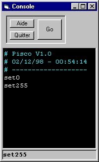
Now, launch the SET255 instruction. This instruction puts all the bits of the printer port data register at the high level.
At this step, you can set all the integrated circuits of the superior board except the CCD.
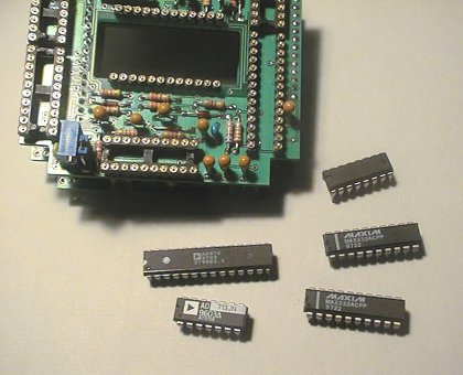
The 5 integrated circuits of the superior board ready to be set.
Remember that you must never set any component when the camera is under tension! To plug the circuits in more easily it is recommended to split the two boards. To do that, separate the two printed circuit boards by small shocks checking that they are still parallel, to avoid that the pins bend. If the pins of the integrated circuits seem not to fit into the tulip sockets, it is probably because they are too separated. Use the flat clamp to bring them back inside and try again.
Avoid as far as possible to touch too much the parts pins with your fingers, particularly the analog to digital converter AD976. Before handling the integrated circuit, contact your fingers to a metallic ground connected to the earth ground to discharge yourself from any static electricity.
Even after having set the integrated circuits into their sockets,
you can check the voltages. Avoid to shake too much not to produce a shortcut.
On this photo, the pin 4 of the quad amplifier AD173 (U6) is tested with
the voltmeter. Notice that the ground is taken on the pin 14 of the CCD
socket. The CCD itself is not already set.
|
|
|
|