|
|
|
Hardware Review
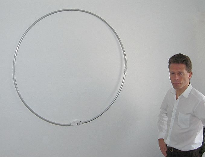
The ALA 1530 active magnetic loop antenna (I) Are you looking for a stealth and short receive HF antenna able to reduce QRM ? Here is one: Wellbrook antenna ALA 1530, an active magnetic loop antenna 93 cm (3') of diameter made of aluminium for about 1 kg (2 lbs.) ! Listening to the lower bands (e.g. AM frequencies and 160 or 80-meter ham bands) with an antenna well cut at 1/4l, what means 40m long on 1.8 MHz, is a length that not everybody can handle and often difficult to install, even vertically, in an ordinary garden of a few tens of meter squared! To listen to the other HF bands, say wavelenghts extending from 40 to 10 meters, with a special interest for the 20-meter band (14 MHz) you need to install either a vertical from 5 to 10m long (1/4l), a dipole cut at 1/2l (the G5RV multi-band dipole is 31m or 100' long) or a beam offering usually a wingspan close to 7m or even longer. Excepting the shortened models, these antennas are not always stealth and you cannot necessary install them where you want without permission and surely not indoors.... Excepting whip and mobile verticals, in this regard the ham market is quite poor. But for a few years, Wellbrook in the U.K. provides several active magnetic loop antennas, ALA models that are true winners : they are performing, compact and easy to install. The low profile of the ALA magnetic loop is very significant as is its feather weight. But not only is it light and compact, but the ALA 1530 is able to "pick-up" SW and LW. You can easily listen to near (5000 km) AM broadcasts down to 500 kHz as well and to many DX broadcast stations emitting on HF (all over the world), and of course all HF ham bands. Then there is the problem that one day or another we all experiment, radio interferences due to man-made noise, the famous QRM and other RFI. Chhhhhrchw …or Tactactactac, do you remember that sound ? Sometimes severe these undesired noise can easily drow out your strongest DX and ruin your listening or drow out all your hope to get the QSL of your most wanted DX... This is not a problem if the source of noise is intermittent or occasional. But that becomes a really problem if the QRM is permanent. If your local telephone and radio administration cannot help you in solving the problem you have no other choice that moving in a quieter place or finding a way to attenuate or eliminate this QRM. At last there is the problem of matching the antenna with the receiver input, in most case that means a 50 ohm impedance to get the maximum signal transfer. Using for example a dipole or even a longwire 20 or 40m long, you cannot get it and you need a balun 6:1 or 4:1 depending on the impedance. It is not mandatory but that will allow your system to work in optimal conditions. Many SWLs do not care of the matching between their antenna and their receiver, and their antenna system is usually of any length, far to be cut with accuracy of each band. They lost a great amount of signal strength, mainly the weakest. However the main problem remains the QRM. Currently in my LX appartment, in the living-room and in the shack I experiment much QRM generated by either a global source of RFI or rather a poweful source located a few tens of meters away, one floor up or just beside. I can made this comparison because in another home I use, among other antennas, a G5RV multi-band dipole 31m (100') long tight horizontally over the garden that picks-up nearly no QRM at all on any HF band. Of course the location explains that; the second one is far from urban environment, on top of hills with fields and forests, and permits me to heard practically all DXCC entities without consulting the cluster. But in my QTH in LX, also located in the country but not as quiet as the second, due to a lack of space I cannot tight a wire antenna over 15m across the garden and I had to find a compromise to receive DX stations. So both installations are not exactly identical. If I install my receiver in LX, I capture too much QRM due to an unidentified local QRM : the S-meter exceeds sometimes S-9, with an average level of S-7 ! In other words the noise is permanent. Even my computer (the keyboard control LED, the screen, the reboot/shutdown phases), the scanner, some power supplies or a digital camera recharger are sometimes also strong sources of QRM. All HF bands are concerned but, as usually, mainly the higher ones between 20-10 m, bands that I use the most for DXing in summer (when the sun and the ionosphere are in good shape!)… So I could not continue and complete my DX awards this way. When I was SWL my first idea was to buy a MFJ-1046 noise canceler but I was not convinced by the result even if it was able to suppress many directional noises. More, the device has to be tuned manually each time that you change of band and even inside a same band due to its short bandpass. So you need to acquire some experience with its three controls to use it quickly and efficiently. This noise canceler is maybe useful but hard to control in some circumstances. So I needed something easier to use. I searched for another solution that I could activate faster and that could perform better in reducing this QRM. So searching on Internet I have found Wellbrook products and its active magnetic loops, receive antennas that, according the manufacturer were especially designed to remove all QRM generated by electrical sources. Was that my miracle solution ? At first sight I had a mitigated feeling about performances of such small antennas. But after have read many articles about the subject and being not an expert either in antenna nor in electronic, I accepted the challenge and for my SWL activities I bought on the suggestion of Andy Ikin, their salesman, the ALA-330 (replaced by 330S now) then, after months of use I exchanged it with the ALA-1530 model, this latter presenting a larger spectrum extending to LW band if not lower. What is a magnetic loop antenna ? In a few words the ALA 1530 is a compact HF antenna constituted of an aluminium sheated loop of 93 cm of diameter. It is especially designed to reduce sensitivity at MF and LF (MW) to prevent the receiver overload from multiples high power AM broadcast in city areas. Complementary its design permit to reduce QRM and other RFI. The secret of this kind of antenna is to capture only the magnetic component (H-field) of the electromagnetic field. An ordinary antenna, a passive element like a longwire or even a beam, works by capturing the electric field (E-field) of radio waves and transmit it to the receiver. However a magnetic loop does not work with this component of the electromagnetic field. When we know that most devices are electrically powered and can generate severe interference in all HF bands, the active magnetic loop looks like a miracle solution as it is, in theory at least, much less sensitive to electrical sources. It is able to reject most locally radiated noises, like mains wiring, air-conditioner, power supply, fluorescent lamps, dimmer, so much sources of man-made noises that we can hear from time to time on HF bands. In practice the QRM and RFI are far to be completely eliminated but in best cases you can expect a reduction that can exceed 4 points on your S-meter or 40 dB ! Intermodulation and dynamic range Like all receive system, the ALA-1530 and in a lesser extent the 330S are sensitive to intermodulation. What's that stuff ? When your receiver gargoyles of thousands noises, the fact of inserting an attenuator (activating the "ATT" button usually) can reduce an interfering signal, and stations until then flooded in the QRM become audible.
Technically your first stage is saturated by two or more stations and the system created products of intermodulation, in other words signals do no more exist; in fact they are multiplied among themselves and fall outside your band. These mixing of frequencies are called intermodulation products of the third order (3d-order IMD). The intercept point is the level at which the range (amplitude) of intermodulation signals equalizes the desired signals; this point is the famous IP3. Between the compression point and the minimum detectable signal level (MDS) we are in the working zone of the RX preamplifier; this represents its blocking dynamic range. In the case of the ALA-1530 and 330S antennas, the dynamic range is exceptionally high. The dynamic of the second and third order intercept points are respectively +70 dBm (IP2) and +40 dBm (IP3). In fact Wellbrook tested the loops with two signals at +10 dBm S9+80 dB output to be sure that there is no risk to work with a preamp offering a too low dynamic range but also to prevent any damage to the antenna active circuit (the white "black box" at the base of the antenna) if you listen to broadcast stations in an area where there are very strong AM emitters at a few tens kilometers around. Assumming that two signals from the ALA-1530 provide S9, 50 mV or -73 dBm, then the 3d-order intermodulaton is -73dBm x 3 + 2x loop IP3 (40 dBm) = -299 dBm. The 2nd-order intermodulation is -73 + -loop IP2 (70 dBm ) = -143 dBm. The above figures assume that there are no other signal higher that S9 in the loop passband. This will never be the case. At last, for two signals at S9+50 dB (-20 dBm), the 2nd-order IMD reaches -110 dBm.and the 3rd-order IMD tops at -140 dBm ! With the ALA-330S the level of intermodulation products are well below the QRN and QRM level what is not necessary the case with the ALA-1530 which is more sensitive to this effect. Compared to a whip antenna, the ALA-330S and in a lesser extent the ALA-1530, improve the S/N up to 20 dB and they are able to ensure a very low level of intermodulation in strong signals environments. Of course such high figures, that break the performances of any receiver, are explained by the fact that these loop antennas use much more less but active components than any transceiver. The best high-ends RTX (Yaesu FT-1000MP Mark-V, Icom IC-7800 or Ten-Tec 525 ORION for example) tops at about +27 dBm for the IP3, thus 23 dBm lower). At last, due to the interference rejection in vertical position these receiving loops display a classical dipole Figure-of-Eight directivity pattern that are enhanced by deep nulls, hence the fact that these antennas are somewhat directive, even installed indoors. Frequency
range
The magnetic loop displays a very wide frequency response requiring no antenna tuning. The ALA 1530 displays a relatively flat response in the frequency ranging from 500 kHz to 30 MHz and matches directly to the receiver without having to adjust the impedance. The impedance machting in not required - it is even forbidden with a receive antenna (see below) - due to the fact that the current induced into the loop is proportional to the field strength rather than to the frequency. According the manufacturer and from my own experience, the useable reception range practically extends from 150 kHz to over 100 MHz. Space
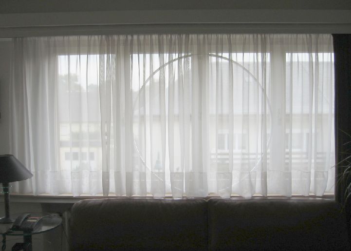
requirement At last like all HF magnetic loops, the ALA antenna is very compact and requires les than 1 meter square in your shack (or outdoor for "all weather" models), practically nothing compared to the required space for any other model of antenna (vertical, dipole, beam, etc). Better, this loop must not necessary to be placed in front of your window or near the balcony. I first placed mine near the window as displayed below but I observed that the reception on the lower bands (40 to 160m) was still improved when I placed it ... at ground level, behind a door near a wall located 3m away from the window ! However according the manufacturer even if the loop can be used indoors and at ground level it performs best if you place it 7 m high and away from noises radiated by buildings. All these advantages made of this kind of antenna the ideal model for people with limited space, interesting in LW and HF listening and experimenting much QRM.
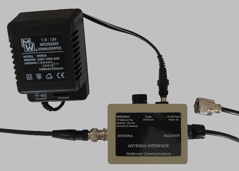
Installation and first activation The product was originally packaged and I suspect the postman to wonder what could hide this huge « hula hop ». Imagine how to transport a 1m-loop by messager : all the loop was envelopped in a thick and dense tube of foam, maintained internally with 2 bamboo sticks ! It arrived some weeks later at home in Luxembourg in excellent state without additionnal charges. Great ! Once the antenna unpacked and seeing no "assembly manual" excepting a small graphic drawed on a technical sheet (the same as the one published on Wellbrook website), I had a few seconds of stress. How could I assembly all that stuff ? The kit contained 1 metallic adapter and three screws to fix the base on an optional mast or tripod, the antenna interface, in fact a small plastic box that I opened to discover it was flooded with "black gelatin", so a true black box working as amplifier on which it was written "antenna" on one side and "receiver" on the other side from which run a small coax RG58C ended with a PL-259 connector. Good, I already recognized the jack to connect to my RTX antenna terminal. The interface had also to be connected to an external power supply for which only the jack was supplied. Although this material looks fine and use quality components this is however a kit for amateur : BNC and RG58C coax are not known to be the best components we can find in a ham shack… On another side these components are know to be more widely used by RF professionals then other types for receiving applications ! Anyway, if all that works I will already be happy. As I wondered why the manufacturers did'nt include better components, M.Andy Ikin explained me than he didn't see any reason to use RG213 and UHF (PL) connectors : "the attenuation difference, he said, is less that 1 dB per 30 m. Also the pressure sleeve BNCs offers good protection against moisture ingress into the feeder". The so-called "manual" explaining how to assembly the antenna was minimalist, and from what I seen the technical sheet was "compatible" with all magnetic loops sold by Wellbrook. So I took the risk to "adapt" the graphic provided with my ALA 330 to my ALA1530, assemblying all parts according what I see on this unconventional and unappropriated user manual. As expected I encounted my first problem : there were neither connectors antenna side, nor power supply, what is a pity for what these components cost (21 € vs. 230 € that costs the antenna charges included). So I wondered why the manufacturer didn’t include these parts in the kit. M.Ikin to answer, "to date, I have not been able to purchase in the UK a 12 volt 200mA Linear regulated power supply with a 230 Volt European plug. I don't provide the coax cable or BNC Connectors because each user has different cabling requirements". But I suspected there was a more pragmatic reason that M.Ikin explained me "Also, the additional weight of the BNCs and feeder cable would double shipping cost and make the antenna less competitive to other active antennas [Dressler and RF Systems for example]". However, Wellbrook provides the PSU for the US market. So in the next hour I had to buy the required accessories : 2 male BNC connectors, 8m of RG58C 50-ohm coaxial to feed it and a stabilized power supply 220/12V at 400 mA or higher with several extractible jacks to the nearest electronic shop. Hopefully the antenna interface came with a fuse (315 mA) and as I told with a short coax ended with a PL-259 connector I immediately connected to my RTX antenna input terminal, beside my dipole terminal that was always connected to compare signals received by both antennas. After assembling of all parts, some hours later I posed the loop on front of the window, 1m high, street side. With its small 1m of diameter the loop is rather cumbersome in a living room or in a shack, but on the other side, as it is very light - it is made of aluminium - it is easy to place it behind the veils or anywhere else, the manufacturer suggesting to place it at ground level. I tested thus various locations in my house after have switched on my Kenwood TS-570D transceiver anywhere in the bands where I could capture an emission. I also remembered the warning of the manufacturer : never use the ALA 1530 or any receive antenna in emission or I should experiment some hardware damage. In fact the small transistors located in the interface will not support the 100 W PEP emitted by the TX and will explode the system. So, sworn me that you will never use these antennas for transmission! Once the loop placed near the window I did various tests : I changed its position in the living room, I placed it on the ground as suggested, more or less near or far from the concrete walls and I changed its orientation related to the signals. I used both antennas at night (23:00 UTC), in the morning (06:00 UTC), in the middle of the day (11:00 UTC), and in the evening (18:00 UTC), thus in nearly in all my working conditions, under all kinds of QRM (local to the room, from outdoor, from broadcasts) and even during bad weather (foggy, wet or rainy). After one year of practice what can I conclude ? Even if using the loop indoors is not a valid comparison with a dipole tight outdoor, results are quite impressive, and still more knowing that this loop is also marketed as an alternative to the active whip antenna ! But see by yourself. Next chapter
|
||||||||||||||||||||||