|
|
|
The mystery of radials
Introduction (I) Many publications have examined the mystery of what effect radials have on the efficiency of antennas. Instead of describing each article, pro or con, what does the "Bible", I mean the various editions of The ARRL Antenna Book, tell us on this subject ? For short, according to exhaustive tests conducted by RCA in New Jersey in 1937, ARRL refers to FCC that specifies that to get a low-loss ground system using a 1/2l vertical, 120 radials equally spaced and each at least an half-wave long extending radially from the base of the antenna are needed on the lowest working frequency. They must be grounded to prevent shock and other damage. ARRL states that using many short radials evenly distributed around the antenna is preferable to few but long radials. On the other side, it is also reported that a ground connection for the HF spectrum may be useless... and somewhere else that in the end a ground screen is still the best solution to get a perfectly conductive ground. At last in restricted places ARRL states that the FCC notes that more than 12 short radials will have little effect on such antennas... but that 15 radials are the minimum required to not lose too much power. In the last edition of its book ARRL suggests to install 16 radials 0.1l long or 36 radials 0.2l long or still 120 radials 0.4l long, hence I will not surprise you in saying that a deep mystery and a dense fog envelop radials ! So taking my pilgrim stick, I am going to penetrate this Terra Incognita in your company (not alone, I am not crazy yet !) to confront this strange animal, Hi! We will survive and come back richer than before once the fog dissipated !
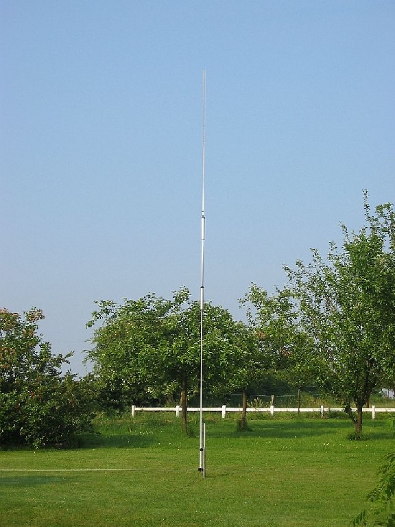
On the utility of radials If you read the other pages of this website dealing with the properties of antennas you know that the ground effect is proven and alters the efficiency of any antenna in increasing its power loss and modifying its radiation pattern. Do not confuse radials with the long vertical or tilted stubs, sometimes over 1m long, used by some manufacturers to shorten the wingspan of their beams (e.g.Cushcraft MA5B or Butternut HF5B Butterfly). Other antenna arrays do no need to be grounded either as they already use elements 1/2l long, straight or folded. Radials are only used with some models of vertical antennas. The antenna must be a quarter-wave vertical, and only this design. They not apply to other models. In theory, all antennas should work against a ground, but the need for that requirement can be mitigated by using a balanced half-wave antenna. The same theory applies to a dipole. These 1/4l vertical need to be grounded first of all to create their "second half" in order to be resonant at 1/2l as explained on the next page dealing with the different types of aerials. 1/4l vertical antennas need also radials due to their vertical polarization and their general proximity with the ground. They are thus much more affected by the ground effects that antennas polarized horizontally (dipole, beam, etc). The first confirmation of the use of radials comes from FCC again who recommends to AM broadcasters to install as much as 113 radials each a quarter-wave long to reduce earth losses. To prove its efficiency Valcom in Canada suggests to install at ground level such a network constituted of 120 radials 34.2 m long (114 ft). Right, excepted that to work on the 40 m band for example, you need a free space of 10m of radius, of course in all directions... I even don't speak yet to work on the 80 or the 160m band... As noted a commentator, the FCC has probably not included in its formula the price of the estate..., Hi! Thus first question, are 120 radials of 1/2l long mandatory to operate with a 1/4l vertical ? We can easily proof the contrary. In the field if you remove all radials attached to your vertical your correspondent will immediately note that your modulation has changed. Your voice will have a metallic sound, more agressive. Then your radiation pattern will be deeply affected, displaying probably a torus-shaped angle of radiation, suited for local QSOs but surely much less effective for DXing. In fact in removing your radials, you reduced the size of your antenna of 50% because these radials are fully integrated in the antenna design. On the 20 m band for example, a vertical of 6 m high like the Fritzel GPA 404 displayed below (that uses 2 trap coils too) must be completed with a 5.2 m long radial, to give a vertical cut at 1/2l; this is mandatory to create its mirror-image and be able to work on its harmonics and thus on several HF bands.
Amateurs also observed that two 1/8l radials reduced the efficiency of an antenna system up to... 75% ! In other words you loose 6 dB, 1 S-point or more, simply in modifying your radials ! But how many radials are really useful ? The FCC himself states that the earth resistance decreases rapidly passing from 15 to 120 radials, advising even, as we seen, the broacasters to use as much as 113 radials. Experiments also confirmed that placing the antenna at a height of 1/4l over ground, the use of 15 radials does not increase the efficiency of the antenna higher than 50%. Different tests also demonstrated that using 15 radials of 1/8l give the same result at if they were cut at 1/2l. At last it appears that using many radials, even if some of them are short, give better results than using few but longer radials. At last, RF technicians tell us that in average half the ground loss observed in a vertical antenna occurs within a circle which radius equals to the antenna height, thus practically 1/4l, and the remaining loss resistance occurs in the next 1/4l out from the antenna due to decreasing of the capacitance between the vertical radiator and the earth. So the radius covered by radials should reach 1/2l... Mixing all these datas and checking what manufacturers designed in this category of antennas, we can consider that 15 radials cut at 1/4l in #12 to #18 AWG are a prerequisit to operate a 1/4l vertical placed at ground level in good conditions. But as we are going to explain below and in the next page, this is probably not the best installation that you can do. The ground effect There are several kinds of radials : those that design a ground plane, counterpoise or acting like capacitance. Generally speaking we consider ground plane radials or the ones acting like capacitance. Indeed, when a vertical antenna is erected at ground level and powered, there are much ground currents generated by the earth capacitance and resistance that increase the effect of the earth on the antenna losses (associated to losses in the transmission lines, etc) that see its radials running at ground level be completely detuned. Radials being part of a 1/4l antenna system, this detuning affects also emissions in increasing the horizontal radiation lobes to the detriment of the inclined lobes. This problem affects also the listening in the same proportions (pick-up radiation lobe horizontal). To get an efficient harmonic antenna with an unaltered radiation pattern, we need an earth resistance as low as possible.
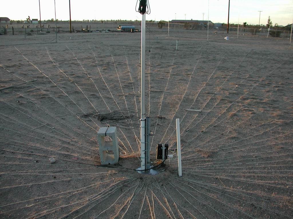
First af all, losses in an antenna depend much on the soil conductivity, below and in front of the antenna : a stony or sandy area is a poor conductor compared to a meadow or seawater. Then placing radials at ground level, on the grass or just below the surface, is a lost battle as your radio signal will have to fight against a subsurface constituted of high resistance material (e.g. sand, sandstone, marble). Fresh water, on the other side, is not a better RF conductor. So in order that your antenna works efficiency avoid to install your shack in front of a lake, a swimming pool, a creek, a river, etc, so many spots that we usually see near antennas... A ground system showing no loss at all is ideal but far to be easy to find or to build in the field. Such a system means that all power applied to the antenna radiator (excepting the few percent lost in loading) is radiated in space instead of being lost as heat. Practically we note that a fraction of the ouput power radiated by an antenna is lost in the coax, traps, coils and other accessories and contribute to warming the Earth, Hi! But another significant fraction falls down from the antenna radiator to the lossy ground. This loss can reach 80% of your output power on the lower frequencies. This part of radiations should be "re-injected" in the system, to the antenna feed point, with as less loss as possible, to be radiated by the antenna in a new cycle. How to proceed ? As told Butternut, "copper-plate your backyard... or use some plain old wire in any gauge".
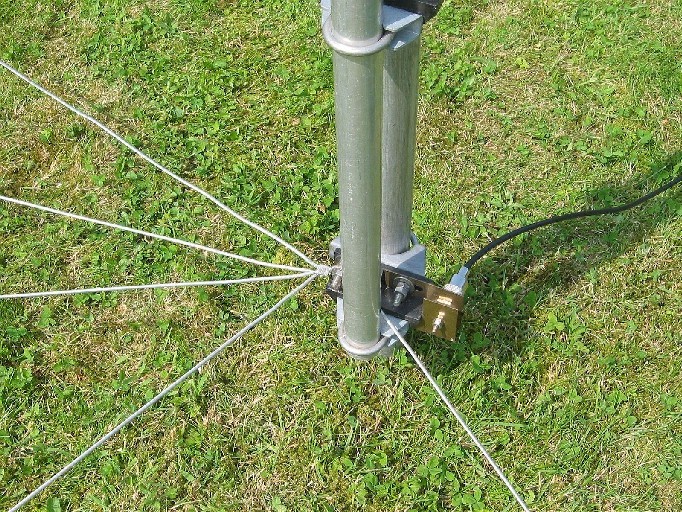
They are perfectly right ! If you lay evenly on your garden, at the base of your antenna, a mesh of copper or steel wires (a wire-netting) on a radius as long as possible, you will create a perfectly conductive ground in which radiations transmitted by your vertical will reflect like in a mirror. Thanks to this dense wire-netting, the power losses will be also reduced because the antenna resistance will be much lower than the one of the ground. This change will also affect the radiation pattern of horizontal dipoles in splitting the main vertical lobe as explaing in the page dealing with radiation pattern. Note that to attach all radials to the antenna ground, DX engineering had the clever idea to provide a very convenient stainless steel plate of 30 cm2 ref. DXE-RADP-1P like the one displayed at left. The antenna base comes inside the clamp. All accessories bought together, this system cost about $62. Using an electric screwdriver, and attaching one radial per bolt, you can bolt all radials in less than an hour. The FCC states that the mesh constituting of radials has to be cut at 1/2l (so displaying a radius of 20 m to work on 7 MHz) to effectively establish the height of the antenna instead of the actual earth beneath the antenna. But contrarily to what wrote FCC, this mesh buried in the ground has not to be at all in resonance to work properly as our objective is to make the ground as conductive as possible for RF signals. So far, when you work with a vertical cut at 1/4l standing directly over a metallic plate (your car hardtop or even using a base like the MFJ-1904 RF ground-coupled base) you do not worry to know if this surface is in resonance or not. As states Bencher, the manufacturer of Butternut antennas, "for mobile operations, according to the counterpoise principle, the metal body of the vehicle provides the capacitive coupling to the earth itself". MFJ Enterprises confirms also that his "ground-coupled portable antenna base, a 2x2 foot stainless steel square, provides an effective RF ground[...]". The same principle applies operating from a boat at sea where you do not expect that the "length" of the underneath open-sea surface is at resonance with your antenna... but rather that it constitutes a perfect conductive "ground", without losses. This "ground screen" plays in fact the role of an electrical mirror, not the one of the node of a string at which standing waves reflect back and radiate ! In fact many people confuse the ground with the antenna itself. To be resonant (what is not mandatory but necessary to match impedances), a vertical is usually cut at 1/4l, and uses its mirror-image to reconstitute its electrical "missing-half". It displays an omnidirectional pattern in the horizontal plane (the current or the radiation pattern increasing from the top to the ground connection, the RF voltage being the highest on top, at the open end of the vertical). This pattern in sine curve has to reflect in the ground, whatever its horizontal extent, to display the same radiation pattern as a 1/2l vertical in free space. Note also that in the ARRL book "Vertical Antenna Classics" (ed 2001, pp.104-107) we can read that "respectable performance can be achieved with radials as short as 1/16 of a wavelength". The ARRL "Antenna Book" (ed 1998, ch.6 pp.27-28) confirms also that for low bands between 1.8 and 7 MHz we can also use shortened radials : "As long as they are not made too short (down to 0.1l) loaded radials can be efficient - with careful design". But in a shortened vertical system, the electric equivalent circuit presents much ground losses. It must thus be balanced by a system offering to the antenna a low capacitance to the earth while keeping the capacitance to the radials. This RF ground coupling is got either in installing at ground level more radials around the antenna base or raising the antenna and its radials above ground, transforming them in radiative elements. On the lower bands this is achieved in using loading coils for matching impedances. Therefore, in the first case, don't be surprised if some amateurs tell you that they buried hundreds of cans in their backyard just to give to their antenna an earth more conductive, Hi! On the other hand, the extent of this artificial ground is, on the contrary, very important when you will emit as the distance up to 10l around your vertical influences much the efficiency of its angles of takeoff. These both aspects are two things completely different. Installation of radials The soil surrounding an antenna or its radials has a very low resistance what entails much loss in transmission lines and buried radials. In the same time due to the soil permittivity and moisture content (water), the capacitance of any buried wire is also much higher than its value in the free space. Both factors contribute to slow down the velocity of propagation along a buried radial to a value as small as 1/12th of the free space value ! For all these reasons it is a nonsense of cutting radial wires to particular resonant lengths if they are buried... At last the attenuation of the current along a buried radial wire is also very high. In average, calculations show that at the lower HF frequencies the optimum length of a buried radial is of the order of 1/10th of the free-space wavelength. Using more radials can however counterbalanced these losses, increasing the efficiency of the antenna system.
Theoretically radials must be constituted of copper wires or thin tubing, cut on particular resonant length, and be located as well as grounded at the base of the antenna, not a few meters way. However, when placed too close to the earth, due to their significant capacitance, any length of HF wire will couple tightly to the earth and will be thus detuned as we just told. Worse, if the vertical is elevated more than 30 cm (1 ft) or so about ground, the wire leading to the ground connection will become part of the vertical radiator and will be no longer in resonance on one or several bands. This is one of the reason for which any radial system has to be place right at the antenna feed point to give good results. Installing it at ground level if your antenna is fixed on top of a tower for example, is in this case a nonsense. The role of these radials is thus to provide paths of low resistance back to the feed point. Practically if your antenna is placed at ground level, to protect radials from lawnmover and human activity, they can be buried just below the grass (over 5 cm or 2" deep to not cut the roots) but do not expect a great efficiency working this way. Take also into consideration that due to the length of waves below the 20 m band, in the lower frequencies it is usually out of question to bury or attach dozen radials measuring at least 10m long and most amateur prefer to select other antenna designs like dipoles. However, a dipole doesn't display the same radiation pattern as a vertical. From the 20 m band and above frequencies, if you want to build a true ground plane with your radials and get good shielding you have to equally space them on the ground over 360° around the antenna. On the contrary, if you are using e.g. a Ground plane antenna with only 1 radial per band, it will act like a counterpoise rather than a ground plane. I suggest you to tighten all radials in the same quadrant, each 10° apart to prevent coupling, in order to get a common directivity on all bands.
As we have just said above, to build a ground plane the number of radials depends on how long they are, the longer being the best. The magic tricks to know is that such wires becoming longer, they intercept the current on the surface out to a greater distance than shorter wires. But in parallel - the word is appropriated - there is a side effect : for a given number of radials, the separation between adjacent wires increases as the wires become longer to avoid low-loss path. Take an example. Four 1/2l radials are preferable to six 1/4l radials but the difference is weak as the intensity of currents flowing out near the end of wires will be much less than that of currents closer to the antenna. According to various specialists, it seems that over 24 m long (80 ft) the gain is no more significant and it is preferable to use shorter radials but more numerous. To confirm this last sentence, using software simulating the ground losses, it appears that by increasing the number of radials from 10 to 20 for example the improvement in signal strength is only 1/10th of an S-point. Some amateurs find it a simple waste of time and copper in doing so. Indeed, stop to wast your time and money ! It is proofed for long times that it is useless to add too many radials at ground level to increase the efficiency of an antenna, because there is a much better solution : raising the antenna above ground to benefit of better performances ! Second part Erecting the antenna above ground and SWR
|
|||||||||||||||||||||||||||||||||||||||||||||||||||||||||||||||||||

