|
Technical review
Class AB
(IV)
In
Class A we have discovered that the ouput power is quite limited and
we cannot reach high signals
while in Class B the ouput signal is more powerful but yield no
linearity, and both classes show a too low efficiency.
As
amateur radio we need power, 100W in input and up to 2 kW ouput
(that depends of your national regulation), we need a linear signal
and efficiency. To get these results, electronicians invented the
Class AB and its derivated Classes AB1 and AB2. Today all linear
amplifiers used by hams belong to Class AB which efficiency does not
exceed 50%, there are tubes or solid-state amplifiers.
These
amplifiers use power devices that are are slightly polarized
so that they work in the linear region of the load line for weak
signals (Class A) and in Class B for stronger signals. In
this way we avoid cross-over distortions as the working point of
transistors or tubes can be placed a bit higher than the cut off at
the lower end of the active region.
This
polarization
is less than in Class A, allowing the transistor or tube to emit
very few current when there is no signal in input. But as they are
somewhat, the linearity is modified. Therefore in all amateurs
amplifiers the output circuit is completed with a filtering function
to cut all harmonics produced in this process.
|
The
amplification
factor of AB2 triodes
The
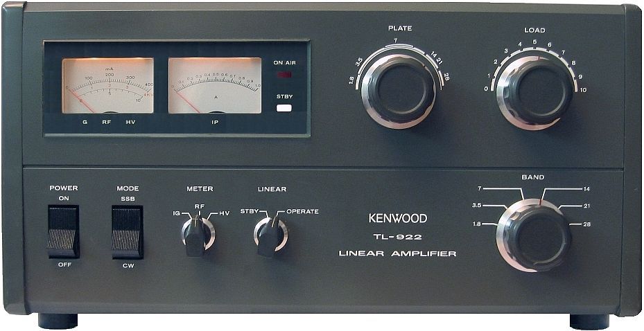
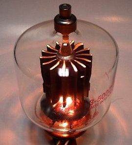
popular 8802/3-500Z triode (mainly found in Kenwood TL-922
and Heathkit SB-220 amplifiers) has an average amplification
factor of 130 (Eimac) to 200 (Amperex). The Amperex version
appears to be electrically equivalent to the 8163/3-400Z
with the exception of the anode dissipation rating. The
maximum-input rating of the Svetlana 3-500Z is 110 MHz. 3-500Zs
work well above 110 MHz if the power is de-rated (usually to
60%) as frequency increases. Other types of modern tubes
amplifiers commonly used in HF amplifiers have an even
higher amplification factor and a frequency rating of up to
500 MHz. The discontinuing 8874 is a good example of a high
gain, 500 MHz triode. It has an average amplification factor
of 240 ! This is definitely a high-m
triode. |
Class AB is subdivided in Class
AB1 and AB2 depending the power stage characteristics :
Class
AB1 concerns a power stage that does not absorb current from the
previous stage; this is usually the case with vacuum tubes without grid
current and the Field Effect Transistors, the famous FETs. This
stage yield usually a high impedance.
Class
AB2 concerns a power stage that absorbs some
current from the previous stage; some vaccuum tubes are used in this manner
and all the classic bipolar transistors.
In
the field it is easy to recognize a ham using a Class AB amplifier
so-called linear. When speaking some of his sentences are grinded
and works lack in the conversation. This effect occurs when the
polarization is too low, with for consequence to transmit only the
peaks of modulation; the current is transmitted during less than
half of a wave of the output signal. To solve this problem this ham
has to increase the quiescent current.
Classe C
A
Class C amplification is requested each time that we need a
powerful signal. With a short pulse at the input, the
amplifier yield a high power. The
signal being biased with negative voltages, the
working point is far beyond the cut off point as displayed
in the graph at right. The
resulting output signal is strongly non-linear and the its
missing part has to be recovered with a resonant circuit
that converts the collector current pulses into a
continuous sine wave. The collector current pulses contain also many
harmonics which are filtered out by the tuned output circuit.
Due
to these drawbacks, such
amplifiers are not used in SSB transmitters. They are mainly
use to increase the RF power level in AM transmitters,
the final stage
being modulated. It is also use
to multiply frequencies by connecting
a resonant circuit tuned to some integer multiple of the input
frequency in the output.
The
efficiency of a Class C amplifier is very higher, reaching
75% in best cases, but this mode generates strong cross-over distortions
too.
Other classes
To
be complete there are several other amplifications classes, Class D,
E, G and H. They are mainly use for audio amplifications by
manufacturers as well-kown as Sony, Hitachi and other
Soundcraftsmen.
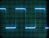
In
Class D used by Sony, the power stage works with square waves which width varies
according to the signal. This modulation is obtained with a high
frequency triangle wave (>500 kHz) mixed with the audio signal.
At every intersection, a wing of the square wave is obtained. Strong
filtering is necessary to suppress the high frequency before it
reaches the loudspeakers and destroys them ...
Although
the efficiency is this kind of amplification is absolutely
exceptional and does not heat much, it presents so much problems
mainly with the filtering that Sony has practically gave up the
project; they only produce a few amplifiers of very high power for
professionals (up to 1.2 kW).
Class D and
Class E concern power amplifiers. They use transistors as switches to
produce a square-wave output at the carrier frequency. As
previously tuned circuits are used to eliminate harmonics and match
impedances. Switching
power amplifiers are the most efficient because they can achieve
efficiencies of 90 to 98%.
 |
 |
 |
 |
|
Sine
wave |
Square
wave |
Triangle
sweep |
TIP31A
BJT transistor |
|
Class
G is a variant of a Class B
combined to a Class C where an additional stage of tubes/transistors
with its own PSU work only during music peaks. This idea came
after having noticed that the peaks in a musical signal are very
short in duration, hence the saving of the power supply. Hitachi
provides such amplifiers that know the same success as
the Class D.
At
last the Class H developed by Soundcraftsmen, is a class G
where the voltage of the additional stage power supply varies with
the signal.
Efficiency
There is always a trade-off between amplifier efficiency (the ratio
of RF output power to DC input power) and linearity. HF amplifiers are generally operated Class AB (180º < conduction
angle < 360º). This is a compromise between Class A (360º, most
linear, least efficient) and Class B (180º, most efficient, least
linear owing to crossover distortion). The devices are biased on to
a standing current sufficient to minimise crossover distortion. It
is possible to adjust the bias for minimum intermodulation
distortion of 3d order (IMD3) by performing a
2-tone test at full rated PEP, and observing IMD3 on a spectrum
analyser during the adjustment procedure.
Do
I need or not of an amplifier ?
Imagine
that you live near a wide open field on a very conductive soil. You
own a good high-end 100W transceiver equipped with all necessary
filtering options to suppress QRM; you own a good antenna system,
probably a beam or a performing wire antenna (long dipole or large
vertical with radials). All is fine until you try to work some far
DX stations located in the middle of nowhere, to say over 10000 km away.
Sometimes you are unable to work them if they not bear their antenna
in your direction.
|
|
|
Kenwood
TL-922, one of the best kW linear, efficient, very robust, it
is quasi silent. It is no more available except on the
second-hand market for a price ranging between 500-1600€.
|
Idem
with pileups or during days of low propagation : you have sometimes
difficulties to work DX stations or to get good reports over 53-55.
That problem occurs sometimes with near stations, located 3000 km
away.
Sometimes
indeed you call, and you wait, wait, and wait to work an interesting
station. In fact your signal is probably sunk and lost among the
ones of hundreds more powerful stations (nearest or more powerful)
trying to work that DX too. When you work in bad propagation
conditions, your signal has difficulties to reach the other side of
the Earth and probably vanishes at some distance of its objective.
How to improve this situation ?
This
problem is not due to your antenna farm that can be directive enough
to work that station if you were alone to work it on the frequency
or when bands are wide open. In such conditions your correspondent,
whatever his location, receive you, but too weakly to get a clear
and loud signal. On your side you hear him, not always loudly, but
at least 53 or with a strong QRK.
So
the sole parameter you can still change is either to work in CW or
increase your emitting power in SSB.
Beside your 100W PEP barefoot transceiver you can add a good
amplifier, up to your class limit, 400W, 1 kW or more, depending
your national regulation. Good news, you will tell me !
Indeed,
when all your ham shack is already invaded with radio gears, SWR and accessories,
that your antenna farm is performing, proved by your hundreds QSL
received from far DX stations, we can say that you have a big gun. Only
in this case the last thing to buy is well an amplifier. Thanks to
it you will not be in a position to increase your
correspondent's signal, that you usually hear 53 or louder with your
beam, but at least you could reach DX stations with ease with the
hope to be heard and to work these stations. But at the
condition to use your amplifier properly. What we are going to discover.
Good
practices
If your RTX is not equipped with performing
filters to reduce QRM, if your antenna yield a low gain or is
omnidirectional, it will be more useful to improve their performance
that using an amplifier. In all cases adding an amplifier to your
current installation will probably not help you much in working far
DX stations that arrive 53 or not at all to you. Improve first your
antenna system, then add some filters (Collins, etc), change maybe
your transceiver for a more complete model and at last, after one
year of experimentation, see if an amplifier is really necessary.
Many
experimented amateurs will tell you too that with a beam and a 200W
PEP high-end transceiver you do no more need of a kW amplifier to
work the world. In this case the amplifier has to be seen as a
useful option to improve the quality of your signal, to get a
stronger QRK to your correspondent, but not really to be heard by a
far DX station as usually they all hear you with your actual
installation, the beam ensuring the most of that work.
Going
up from 100W to 1 kW PEP you increase your signal of only 10 dB. And
practically you cannot get higher powers (10 kW or so). So to gain
some dozen or hundreds watts or a few S-units and be able to work
some far DX stations, the best thing to do is first to optimize your
installation to get the higher output as possible is reducing all
loses : use a low loss coaxial line, work with an antenna well
tuned, and able to sustain high power, get the lowest VSWR as
possible, use an antenna offering low take-off angles, etc. These
are as much features that will increase performances of your
installation for a given power. These advice are wiser than using
an amplifier at all costs and be unable to hear your correspondent.
Using
an amplifier requests to understand how work such a device, you need
to read some books about that subject and about accessories
(antennas, line, SWR, etc), and try to find a near friend or a radio
club to whom you can find anwers to your questions.
 |
|
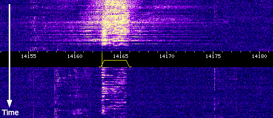
When
the power does not help to work DX stations. This
screendump displays the waterfall spectrum of two
kw-stations (EA then RA above the center) calling
VK3MO, Ian, on 20 meter on June 2015 compared to the
spectrum of Ian (below) using a 20
element stacked beam and 100W. Clic on the
image to listen the two kw-stations calling and
not taken and clic
here to listen VK3MO in QSO with W3WC some minutes
earlier, supporting QRM with much calm and patience. |
|
In
a few words, if you badly tune your system, you will make QRM in
broaden your working frequency, you will overheat both your
transceiver and amplifier, and you will probably saturate your tubes
without working more stations. This does not respect the ham spirit and is not very
useful.
Overdriving
your amplifier, you can also damage it, dissipate much heat and,
worst, due to the high power generate QRM that your neighborhood could
detect while watching TV and not appreciate at all.
You
have also to know that a HF amplifier is an expensive accessory,
usually almost as expensive as your transceiver if not more if you
want an auto-switching and automatic model. High-ends are also
cumbersome (45x40x10cm) and very heavy (over 30 kg). Know also that
for the price of a good kW amplifier you can buy a rotor and a
small beam or even stacked beams.
So
before deciding to buy an amp, check twice if all your equipment
cannot be improved in a way or in another and if you own all
accessories to check the output power (an external SWR-meter up to 1
or 2 kW, a dummy load, etc), and begin in reading technical
documentation about amplifiers and how shortwaves propagate in lines
and antennas. Last but not least, do never use your amplifier to run
over the others amateurs.
For
more detail I suggest you to read my two others pages dealing with
the tube amplifier
and the solid-state amplifier.
It's QRO !
For
more information
How
a Vacuum Tube Works, Svetlana
ND2X's
power amplifiers pages, Paul S. Goble, III
Transistors,
by Williamson Labs
Semiconductor
amplifiers, by Deutsche Welle
Frank's
Electron Tube Data Sheets
Eimac
power tubes catalog
How
amplifiers work, by How Stuff Works
Amplifier
basics,
by Rod Elliott - ESP
Amplifiers,
by GSU
RFParts
Back
to Menu
|
