|
|
|
Hardware review
How to select a HF transceiver ? (I) On what basis can we select a HF transceiver ? What features made the difference between a mid-end and a high-end model ? Is the price a good indicator ? Are DSP functions useful ? Is the touch screen a good alternative to controls ? Is it better to install mechanical filters or a DSP filtering ? Is the selectivity and 3d-order IMD important ? Here are some among the thousand questions that run through our mind when we decide to buy a new RTX. We will discuss in this article about desktop HF transceivers, and what makes the difference between a mid-end and a high-end transceiver. If you are not at the top of the novelties in reading regularly ham magazines or speaking with friends in radio clubs, you will have difficulties to have a deep knowledge of the technology used in new transceivers, how it performs against the older models, especially if you are not interested in the new developments in both hardware and built-in software. In a transceiver, the most important module after the transmitter is of course the receiver. Emitting a signal is not really a problem. It requires few components and sometimes even not much power (QRP). The receiver on the contrary is a very complex module. If you can quite easily send a message using the transmitter, you need a performing receiver to detect the weakest signals emitted by your correspondent, and the few microvolts displayed on the S-meter are really not much energy to pick up. Therefore the performances of a transceiver depend first of all on the quality of its receiver. There is first its sensitivity, the minimum input signal required to produce a specified output signal, under which threshold you listen only to the electronic noise of components or, at best, the noise on the frequency but no readable signal. The second quality factor is the selectivity. RF Power : PEP vs RMS Both values, PEP and RMS, describe the capability of the RF high power amplifier and can be expressed in dBm (logarithmic values) or in Watts ( linear values). The PEP value is important to know for regulatory purposes. However several manufacturers does not give the PEP value but the RMS one.
The RF output power of a transceiver is usually given as the peak-enveloppe power or PEP. It is related to the envelope modulation under normal operating conditions and it can be constant or non-constant. In the first case the PEP power = RMS (root mean square) power. In the second case, PEP power = RMS power + PAPR power (peak-to-average power ratio). Note that PEP, RMS and PAPR values do not depend on selected bandwidth (e.g. 2.4 kKz, 12.5 kHz, etc). FCC has defined the PEP power as the RMS value of a single RF cycle at the crest of the modulation. PEP is equal to the average power emitted in radiotelegraphy (CW), RTTY, FM and FSK transmissions. In SSB operation, the amateur radio never reaches the PEP peak power. In fact, even with the best tuning, the average power of a voice transmission ranges between 10 and 50% of PEP and can reach ~75% using a speech processor. In modern transceivers, the PEP power level can be adjusted with the ALC knob (automatic level control) The RMS value is used in link budget calculation, because the sensitivity levels are given in RMS notation and expressed in DBm. For example, the gain of a system [dB] = RMS [dBm] - Sensitivity Level [dBm] = 37 dBm - (-100 dBm) = 137 dB. The selectivity of the receiver represents its ability to respond to a tuned station and to reject any nearby undesired signal. This is probably the first feature where your receiver will show its limitations, or its performance. The next one will be the DSP.
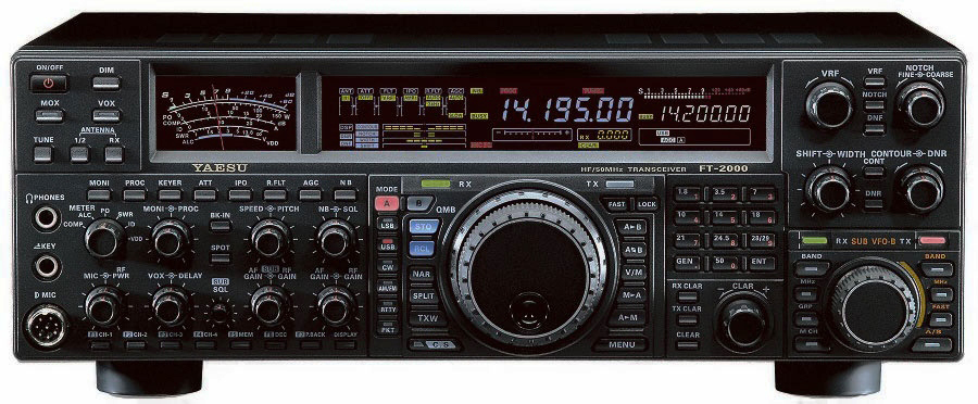
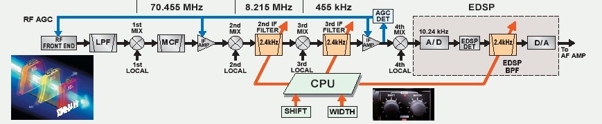
We have also to make the distinction between modes of traffic. The response curve of a filter is defined by its bandwidth at different characteristic attenuation levels (0, -6, -40, -60 dB). Such a curve displays scarcly the rectangular shape of the theoretical model, but a sort of bell shape which wings are more or less abrupt with skirts more of less short. Some of the best mechanical filters are Collins. These filters are inserted all through the receiving chain at each IF stage. If we take the example of Yaesu FT-1000MP Mark V, in CW a narrow filter of 250 Hz of bandwidth at -6 dB (700 Hz at -60 dB) is enough to work all pile-ups and weak stations submerged by QRM. But in SSB, the signal is much wider. The narrowest IF passband is 1.8 kHz wide at -6 dB and 3.6 kHz at -60 dB. You can't thus get similar results in SSB and in CW. On the Yaesu these filters are installed at the second IF at 8.215 MHz and at the third IF at 455 kHz. Like on all transceivers they can be combined in cascade to form the equivalent of one filter showing a variable bandwidth (called VBT to Kenwood). In some books we read that a filter would works better if signals applied to it are weak. This is not true because the response of a crystal or ceramic filter is very linear; it responds exactly the same way to large signals as it does to small signals. This means that whether the signal applied to the filter in within the filter's passband or not, the amount of signal appearing at the output of the filter is proportional to the input signal applied. The method to suppress these undesired noises (they are static noise or RFI) consists in rejecting them outside the passband or, if they are on the same frequency, to attenuate the interfering signals as much as possible before they reach the RF amplification stage.
As you cannot change the filter passband, you need to apply one to three cascading methods to remove all interference and noise that prevent you listening your correspondent in good conditions. Let's describe each of them in a few words illustrated with some graphs. High and Low cut settings The first method consists in shifting the passband of each filter up or down in frequency until the noise has disappeared. So the signal is now in sandwitch between the two filters, rejecting the interfering signals outside the passband (see graph B. below). This technique does not modify the beat frequency oscillator (BFO) tuned on the remote station frequency, so the signal sounds normal. You can also use the High and Low cut controls to remove undesired audio high and low pitch from the desired signal and thus reduce or remove interference as well.
Attenuation and RF gain But this solution does not work if the interference is at the same frequency as the desired signal. To remove the interference without rejecting the signal, you need to apply a second method, the attenuation, displayed above in the center graph. Thanks to the RF attenuator (ATT control) adjusted to 20 or 40 dB for example depending on the strenght of the noise, you could lower the intensity of all signals until the interference reaches the background noise hash. In these conditions you will reduce the generation of undesired products. If this is not enough, you can cascade it with a low RF gain until the interfering signal is removed from the passband, offering you a chance to hear your correspondent without QRM. If you still heard the RFI you can in addition adjust the High and Low cut controls to reduce the passband to less than 1.5 kHz or so, while keeping the BFO frequency close to the passband. However, adding more attenuation and reducing the RF Gain have one drawback. In many receivers there is a poor audio circuitry following the detection stage, which results in excessive noise (hiss) being added to the desired signals. The gain that you reduced on one side has to be made up for elsewhere. If the signals are not already above the AGC attack threshold for a same amount, a significant amount of audio gain must be applied to maintain the desired listening levels at the speaker output. Consequently, this audio gain will increase the amount of hiss present in most receivers. This means that the operator has to manually adjust the AF or RF stage in order to maintain the desired signal levels under fading conditions. To check : Run WebSDR to test the IF Shift on real QSOs
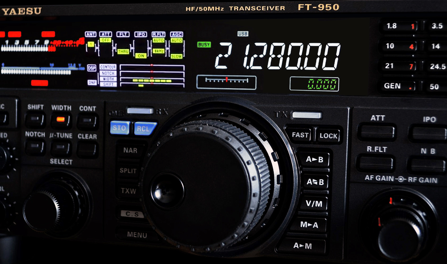
Yaesu FT-950 and all its controls. Document EC1DJ "MrDJ". IF Shift Till now we haven't modified the BFO frequency that was fixed in relation to the filter center frequency. The BFO was set at about 1 kHz or a bit more up or down from the IF center frequency. Now, in some conditions, you can hear both interference and noise on the frequency, tunes as well as static nosies. In the worst case all signals are on the same frequency. To remove these undesired noises you have to use a third method, this time the IF shift as displayed above in the third graph at right. In most cases you will have to cascade all three methods, playing with together a string attenuation, a low RF gain, adjusting the High/Low cut, and at last setting the IF shift to some hundreds of Hz above the filter center frequency, and adjusting the RIT to properly position the BFO close to the passband. In most conditions, in using this approach you will get a reception free of noise and interference. However, if a strong interference gain access to the amplification stage located behind the last IF stage, you will hear it loud and clear in your headset. To remove it modern transceivers are equipped with a fourth IF stage, called the DSP. We will come back on this technology later when we will discuss about high-end transceivers.
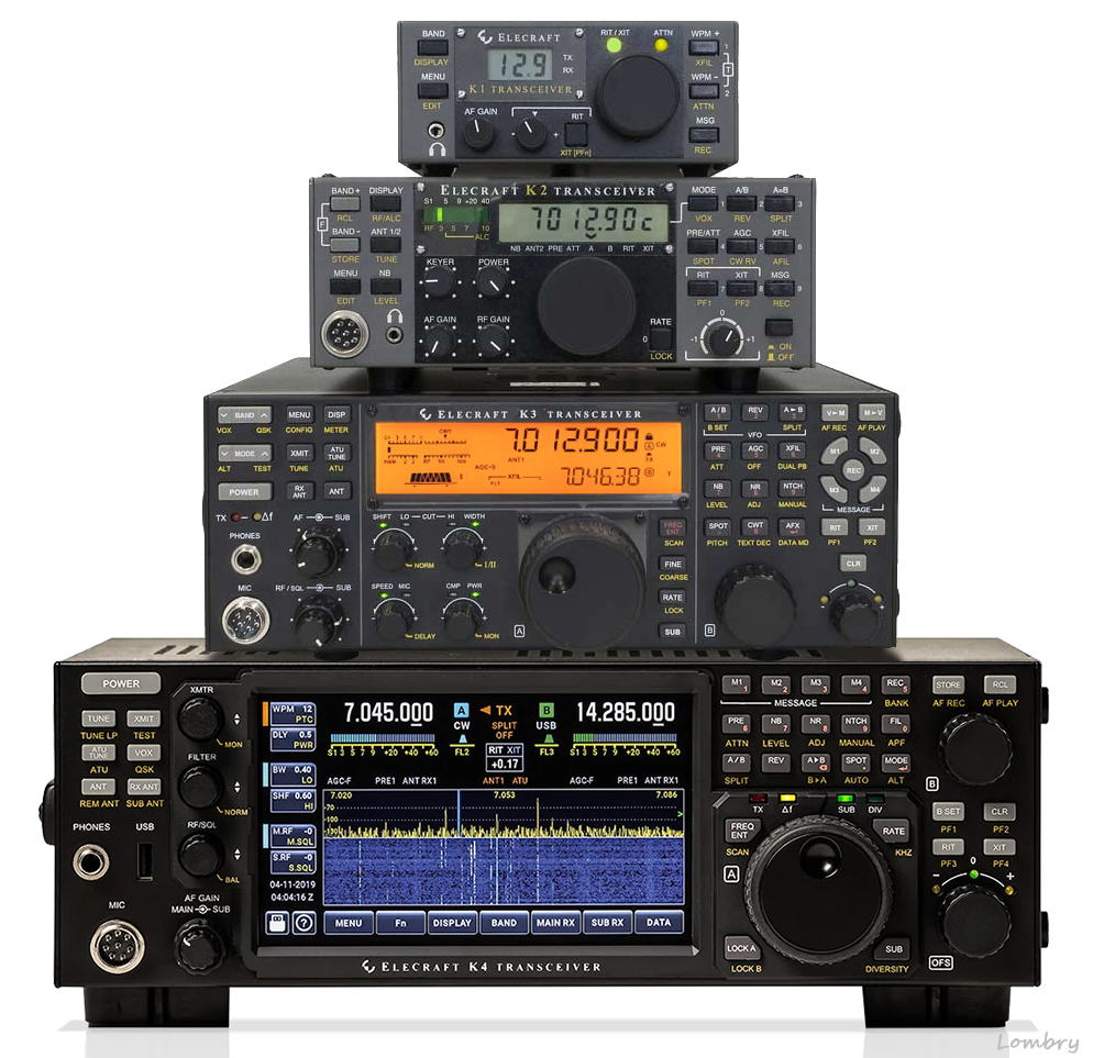
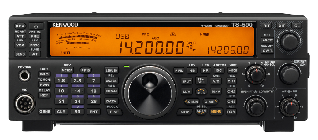
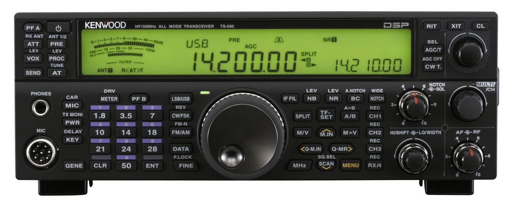
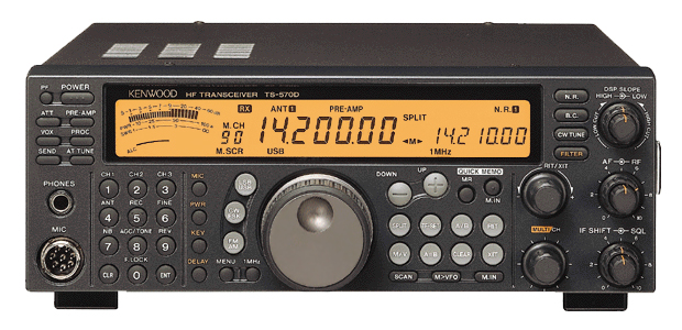
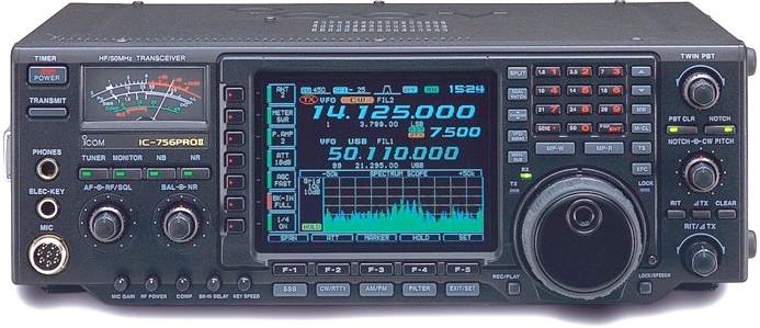
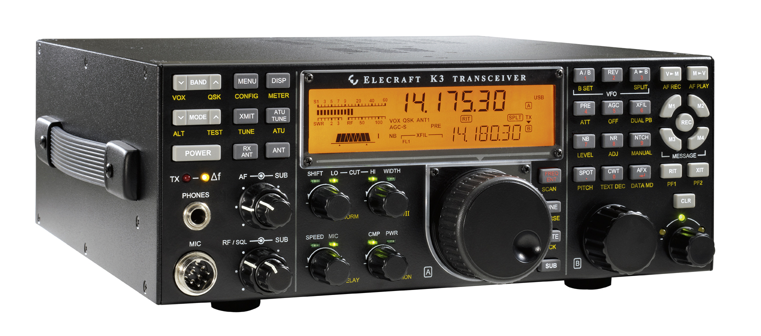
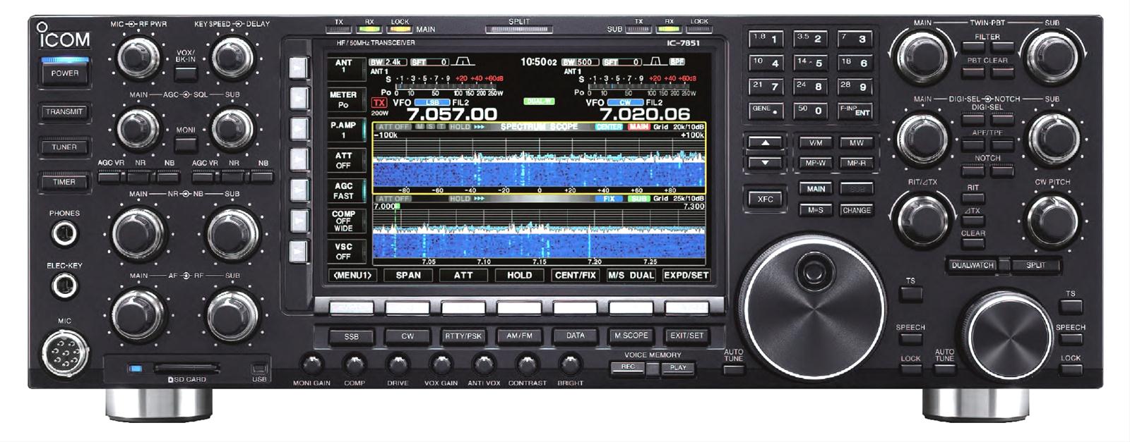
Competition between transceivers Now that our transceiver is equipped with two or more IF stages, each of them taking advantage of the finest filters, let's see what are the different features offered in some well-known transceivers, and some of their respective performances in order to well understand the difficulty of selecting a transceiver suited to your needs. To clarify the problem, we will compare different transceivers used by amateurs. On one side the mid range Kenwood TS-570D, famous of its performances and sold at an affordable price ($1100 or 1700€ in 2002), and on the other side high-end models like Icom IC-756PROIII and Yaesu FT-DX5000MP at prices close to $3000 up to Kenwood TS-990S at $8000 and even the overquoted Icom IC-7851 at $17000 plus options in 2014 ! Are these models worth their price and do they display all similar performances ? We have a tendency to believe that in a same category all transceivers are on par, even if their price fluctuates somewhat from one brand to another. But it is an opinion posed a priori, and a subjective feeling far to reflect the reality of the field. Performances of mid-end transceivers Take Kenwood TS-570D for example. It is a compact desktop HF transceiver that received good reviews, efficient for casual, non-contest operations. In short, its DSP noise reduction is great, and with the optional 1.8 kHz SSB filter, selectivity is good – a reason I bought it contrarily to the opinion of some hams ! But under stress, to carve your hole in a crowded band, to work a pile-up or when the atmospherics (QRN) are strong, TS-570D shows its limits due to its receiver noise level and its limited number of filtering means to discriminate two nearby signals, one being much weaker than the other. In this context, its successors TS-590S released in 2010 and specially TS-590SG released in 2014 are much more efficient with a larger dynamic range, TS-590SG including the IF DSP AGC technology developed for the Kenwood TS-990 transceiver. However, even this TS-590SG cannot struggle against an Elecraft K3 that displays better figures, a better audio, and is more accurate for a lower price.
In fact, three factors limit the receiver performance : - the blocking dynamic range : also called "blocking gain compression" is for short the range between the weakest and the strongest signals that a system can handle simultaneously without noticeable degradation in performance (thus without activating any filtering or attenuator). The value is good from 100 dB and excellent from 125 dB for an offset of 2 kHz. Note that on high-end transceivers, the blocking dynamic range is not listed, especially because on direct-sampling SDR's, the ADC clipping is the limiting case. - the 3d-order dynamic range (IMD) : related to the intermodulation distortion, it is a measure of the 3d-order distortion generated when two tones are closely spaced in frequency and are combined into the same input. If the filtering system is unable to separate both signals, it causes interferences and signals cannot be discriminated. IMD should be read in association with RMDR. Usually IMD is a bit lower than RMDR at the same offset. The dynamic range is good from 90 dB and excellent from 100 dB for a offset of 2 kHz. - the reciprocal mixing dynamic range (RMDR) : it defines the strength at which the filtering system can cope with a strong signal near the current frequency, taking into account the (low) noise generated by local oscillators. Higher it is, better is the gain from the phase noise. The value is very good from 100 dB for 2 kHz spacing and excellent from 120 dB for 2 kHz spacing. Up to these last years, RMDR was rarely listed in reviews.
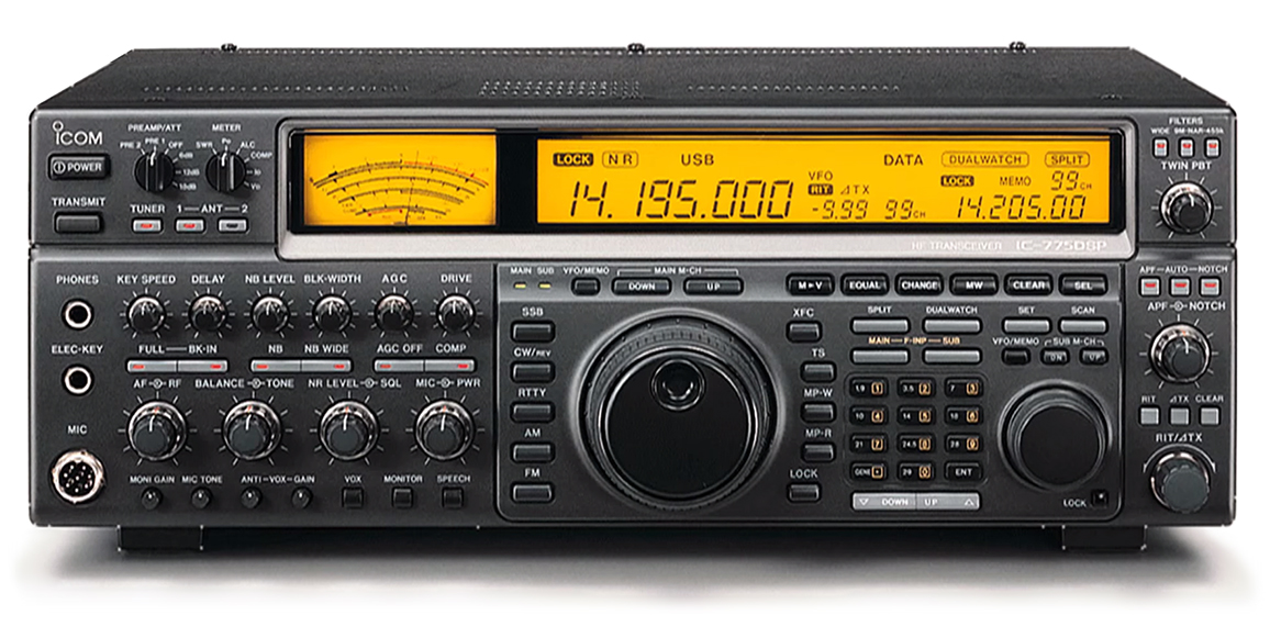
While many systems use DSP technology, in TS-570D among others this processing is installed on the AF stage rather that on the IF one. This presents some drawbacks when the receiver tries to remove interferences or even simple tunes on a near frequency that successfully passed through the all chain of detection. Take now the Icom IC-775DSP, a high-end HF transceiver recently discontinued but from time to time available on secondhand. The main reason to purchase this model with its options is to participate in more contests and penetrate through pile-ups. This is where the Icom excels, and still more equipped with all optional filters. But even using its default settings, IC-775DSP allows narrow filters at two IF-stages where TS-570D allows only one. What is the result? The Twin Passband Tuning used in conjunction with the two 1.8 kHz filters of IC-775DSP is far superior to the IF Shift method offered on TS-570D. With the manual notch filter, there is almost nothing you cannot filter out, another feature not available on TS-570D. On 160 m also, when adding attenuation, turn off DSP, you can open the filters to 8 kHz for hi-fi audio, what TS-570D could never perform. Under strong Q-signals, IC-775DSP receiver does not overload or desense like the much cheaper TS-570D. The sensitivity is about the same, as you would expect because TS-570D is really a great rig in its category, providing an excellent signal and a good reception in usual working conditions.
As explained previously, when the propagation is open and no QRN at all on the band, filtering is even useless and both rigs yield the same results ; they are really on par. So, before reselling your TS-570D, think rather twice than one as it can be a great performer for working abroad, e.g. on holidays or in the field as a portable RTX (even on dry battery) although IC-775DSP is still small enough to be portable but it is much heavier. On the other hand, while contesting or trying to penetrate into pile-ups against world class competitors, you need together powerful tools to remove the QRN generated by near amateurs calling, possible QRM (weather conditions and specially static), and preferably a directional antenna to pick up the weakest signals (note also that contrary to a general opinion, in CW you need a better receiver than for SSB, specially during pile-ups). In practice your system must be able to discrimine any incoming signal without be bored by near strong QRM. To reach these two objectives you need a high sensitivity, excellent 3d-order IMD, a high RMDR and the best selectivity. With these objectives in mind, the small TS-570D will think seriously to give up the fight. Contrary to IC-775DSP, that once equipped with all optional filters in its two IF-stages can have unbelievable selectivity and audio compared to many other rigs. But it is however not as selective as Yaesu FT-1000MP Mark-V or the more recent Yaesu FT-DX3000. This last has indeed more IF stages and more filtering features to fight against interferences. But take also care to the frequencies used by IF stages. In many high-end transceivers, and even TS-570D, the IF stages are outside amateur bands (around 73 MHz, 8.8 MHz and 455 kHz) and they cannot disturb your QSO. But is some so-called performing mid-ends, like the Elecraft K2 to name one, there are a lot of images right in the 15 and 17 meter bands... This is a problem too rarely brought to the fore but that spoils all the interest of this later model.
At last, as far as ergonomy is concerned, the cheap TS-570D is menu driven, without many direct functions, which slows down operation in contest or strong pile-ups. On the contrary, in most high-end transceivers all common settings have a control, even of small size, on the front panel, sometimes highlighted with a LED, giving them a very "high-tech" look, what will not deny James Bond, Hi! Filtering : DSP or Audio stage ? If you are only interested in CW, a filter placed on the audio stage is more than enough to get good results in most traffic conditions. Autek QF-1A is for example an excellent product. But as we explained in reviewing Yaesu FT-1000MP Mark-V, a DSP doesn't work the same way, and in SSB for example it is able to remove automatically carriers that fall in the current passband, and this without using a notch circuit... a great improvement. The passband of a DSP is also programmable to get abrupt wings contrary to an audio filter that displays usually a bell shape. The first is thus "better", in theory. To read : Intermodulation range and roofing filters, by QTH.com (PDF) Receiver Performance Transmitted BW Contest Fatigue, by R.Sherwood, NC0B (10 MB PPT)
At last, the elimination of noise is ruled by signal processing protocols (maths), whereas an audio filter depends on its bandwidth... which affects the audio and therefore, it is not always suited to the mode used. In selecting a filter, keep in mind these reference parameters when comparing performances of your filters. Remember also that not all mechanical filters display the short skirts of the Collins and many are not worth their price. So, generally speaking we can thus say that a DSP is more versatile as it can be used with most modes of traffic than mechanical filters. Performances of SDR transceivers Progress continued, after have used the classic technology until the years 2000, nowadays most transceivers use many DSP functions and display a LCD screen. But it is only since the 2010's or more recently that all major manufacturers have designed transceivers using a touch screen, use much less controls than the previous generation and much more digital stages, as many features than improve the quality of operations.
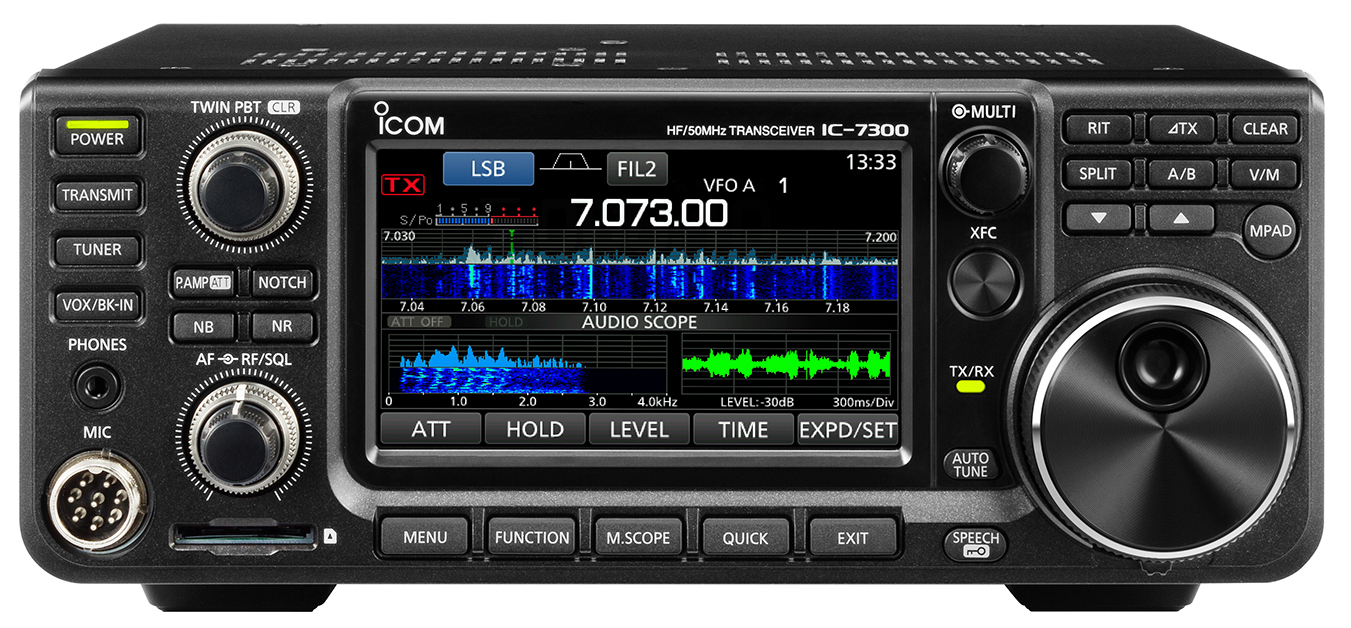
Take the example of the mid-end Icom IC-7300 transceiver released in 2016 and displayed below. It is a transceiver covering the HF bands + 50 MHz with 100W and optionally 70 MHz with 50W. It is able to receive from 30 kHz to 74.80 MHz. It is a model both compact (LxHxD: 240x94x238 mm) and light (4.2 kg, 43 % lighter than Kenwood TS-590SG). Although it is small in appareance, its technology is really amazing and supports easily the comparison with models such as IC-7851, Kenwood TS-990, Yaesu FTdx-3000 or Yaesu FTdx-5000. IC-7300 is the first entry model using the direct-sampling SDR architecture to process digitally the incoming signal to reduce the inherent noise usually generated by the different IF stages. With such a model, you have all in hand (or on the scope) to prevent most unwanted signals from AGC non-linearity to IF chain IMD. Only the AD converter (on 14 bits) till limits its performances when processing RF signal in receive. To
watch : Review
of Icom IC-7300 To read : Technical test of Icom IC-7300, AB4OJ
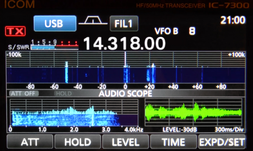
As we can see above, it is also the first desktop model where standard controls (e.g. band selectors, filters, etc) were replaced by a digital equivalent available on a large color TFT touch LCD screen of 4.3" or 110 mm (96x55 mm wide). Only the essential controls remain on the front panel (Power, RIT, SPLIT, A/B, NR, Menu, Function and some others). The level of integration is very high. In addition, IC-7300 displays on the same large touch sceen a band analyzer and an audio scope, and on request it can display incoming or transmitting signal to show the possible QRM, noise and other distorsions, very useful when you work a pile-up, with an amplifier or testing a new microphone. In addition it includes an USB and a SD-card ports without to mention the possibility to control a remote antenna. What else ? We can add that its integrated antenna tuner is the first Icom model using switched capacitors instead of variable ones. It is able to match loads showing a SWR up to 10:1 (in emergency mode). Performances of this mid-end transceiver are in the "good average" with a Blocking gain compression of 123 dB, a 3d-order dynamic range (IMD) of 94 dB/2 kHz spacing, and a RMDR of 97 dB/1 kHz spacing (RMDR for Yaesu FTdx-1200 is 81 dB, IC-7100 is 84 dB, Kenwood TS-590SG is 94 dB, IC-7851 is 116 dB, and Flexradio FLEX-6700 is also 116 dB according to QST who used a 2 kHz spacing). Let's see now how perform digital functions when they are used in high-end transceivers. Second part The competition between high-ends
|
|||||||||||||||||||||||||||||||||||||||||||||||||||||||||||||||||||||||||||||||||||||||||||||||||||||||||||||||||||||||||||||||||||||||||||||||||||||||||||||||||||||||||||||||||||||||||||||||||||||||||||||||||||||||||


