|
Technical
review
How
to select a tube HF amplifier ? (IV)
Security
issues
Due
to the high energy flowing in a power amplifier, several protections
have to be implemented to prevent any damage due to a malfunction or
a bad manipulation from the user. For short, any power amplifier
should be at least equipped with the next four safety systems : a step-starter,
that starts the power supply gradually (in about 2 min), in order to protect
electrolytics' load and rectifier diodes. Such mechanism can also be
found in the filament transformer; a high tension control
that prevents the amplifier to work until turning on the high
tension button; a stand by knob that, sometimes, cannot be activated
before having pressed the high tension button and an interlock
relay that disable the power supply in case of the cabinet is
opened. In addition several other devices that we are going to
discuss are welcome.
 |
|
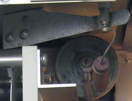
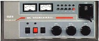
Four
safety systems are installed in Ulvin
Tremedus and some, but still too few, other
amplifiers : from left to right the step-starter, the
high tension control, the operate/stand by knob, and
at last the interlock switch. |
|
Step-starter
Some
kW amplifiers request a warming that can last 2 minutes, what could
surprise novices. In power amplifiers step-starting
is a must. This is required for the plate supply. If a voltage adjustment
resistor is not used in the filament transformer primary, the
filament supply should then also be equipped with a step-starter.
Interlock
relay
What's
the matter if you open by curiosity the cabinet of an amplifier when
it is powered up ? Statistically speaking you have all chances to
get... a fatal accident. I remind you that the DC voltage exceeds 10
kV and some dozen amps. So to avoid to be electrocuted, any good
amplifier must be equipped with a fast relay able to disable the
power supply if the cabinet is opened while the unit is switched
on. This is the function of an interlock relay that must always
be enabled to prevent any accident if by mistake you touch a device
under high voltage. So be very careful if you have to open an
amplifier powered up. Usually this action must never be carried out
at home but only at the dealer workshop or in the company of a radio
technician.
Grid
trip
This
circuit is a must that we should find in any amplifier using power
tubes. Its function is to protect the electronic in case of
overdrive, high SWR or
if a mis-tune happens by mistake. It disables the amplifier until it is reset and
the problem is corrected..
ALC
An Automatic Drive Level Circuit, ALC for short, is designed to
limit the grid current. It prevents overdrive by
applying a negative DC voltage back to the exciter, what reduces its
output level. In high-ends amplifiers the ALC is able to sense as
low as 50 mA
of grid current.
Most
kW amplifiers require a drive level between 50 and 80 W (or 80-120 W
if you use a Kenwood TL-922) to achieve
full output power. The ALC circuit can be internal or external,
manual or automatic. In all cases it is recommended to select an ALC
offering an adjustable threshold control of the output power. If
external ALC is not used, the output of the transmitter must be
reduced using the power output control to avoid damaging the tubes.
Some ALC circuits (i.e. Emtron) also produce a 1-10 V negative going
voltage, proportional to the grid current, but only when overdrive
is present.
Note
that not all transceivers have a direct ALC EXT/RL CONT output on
the rear side. The Kenwood TS-570D(G)S
for example replaced these terminals by a single 7-pin DIN plug that plays
the same role; called REMOTE, it must be connected to the amplifier
ALC/RL terminals thanks to a dedicated cable provided by Kenwood. On
the contrary, the Yaesu FT-1000 MP Mark V for example has a built-in
ALC cinch among others terminals.
Meters
To
get permanently a status of current flowing in your amplifier, you
need a display including some meters, among which the most useful
are a dedicated grid current meter and a plate
current meter. You can optionally use a high
voltage meter. If you work with tetrode or pentode amplifier you
should add a screen current meter position.
It
is recommended to select an digital bar graph metering if you search
for a fast reading. But usually its resolution is lower than a good
analog meter.
These
meters must be protected from parasitic or flash-over in
installing back-to-back diodes and RF by-pass capacitors across
the meter. This last prevent random RF from damaging
the meter movement.
 |
 |
|
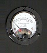
At
left, the Emtron DX-3
digital display. Plate current, plate voltage, output
power, reflected power, screen grid current, SWR,
overdrive, ready, transmit and fault information, for
short all parameters are displayed on this sophisticated
solid state display panel utilizing colored LEDs. A
right, a classic plate current meter. If you prefer a mix
of both displays, may be will you be interested in this Ten-Tec
422 Centurion hybrid. |
|

|
|
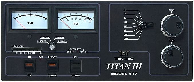
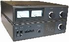
This
metering displays plate current, plate voltage, grid
current, forward or reflected while the LED bargraph
displays the peak power. |
|
Blower
In
a power amplifier we find many components and devices radiating heat,
beginning with the tube(s) and to some extent transformers, and
largest capacitors.
If
you want to cool these units with efficiency a wheezy fan is useless
and your system will power off after a few minuts of work or worst,
the tubes will break. What you
need is a power blower rotating at high speed which specifications
are in respect with the volume to cool or the manufacturer
requirements.
To
get an idea of the heat dissipated by a tube amplifier, an old model
like the Kenwood TL-922 sustaining 2 kW PEP uses a blower model
Centaur CT3D55F using a ball bearing and powered on 100V for a power
of 8W at 50 Hz. In operation it blows an air so warm to the outside
that after some minutes of use you do no more need of a heater in
your hamshack ! Indeed it has to reject half that power out, and is
thus well equivalent to a 1 kW electric heater ! The chassis located
the nearest to the tubes and the fan are so hot that it is
practically impossible to let your hand on them... Of course, due to
this heat the space behind the fan must be free of objects on a
distance of about 30 cm (1 ft). This demonstrates that to cool the
tubes of an amplifier you fan must answer to accurate
specifications.
The
main problem that you could experiment using undersized fans is the
low intensity of the air flow. The second problem, in using larger
models is that they can produce much more noise. At last the
blower rotation speed must not be too high to prevent an
overcapacity and too much noise too. This latter effect can be
substantially reduced in using a large ball-bearing fan/blower. All
these constraints lead to select high grade blowers able to handle
manufacturers specifications.
 |
 |
|
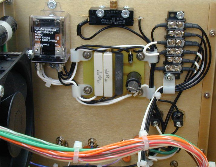
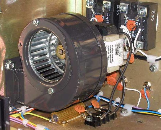
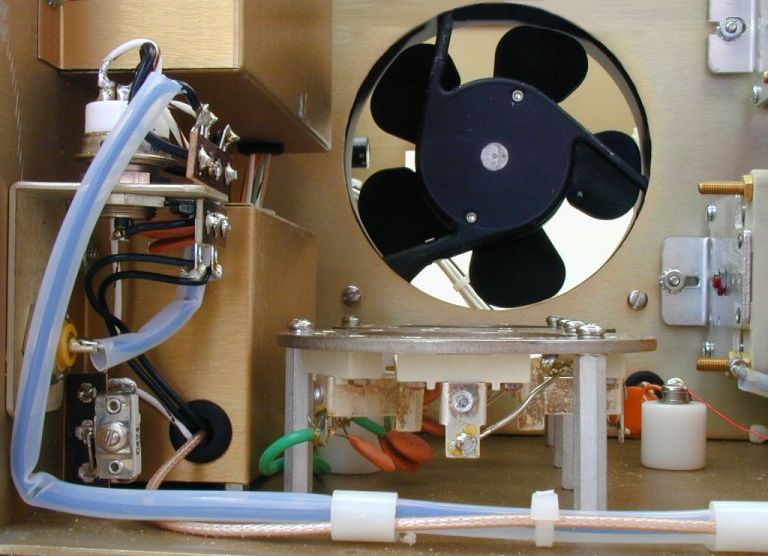
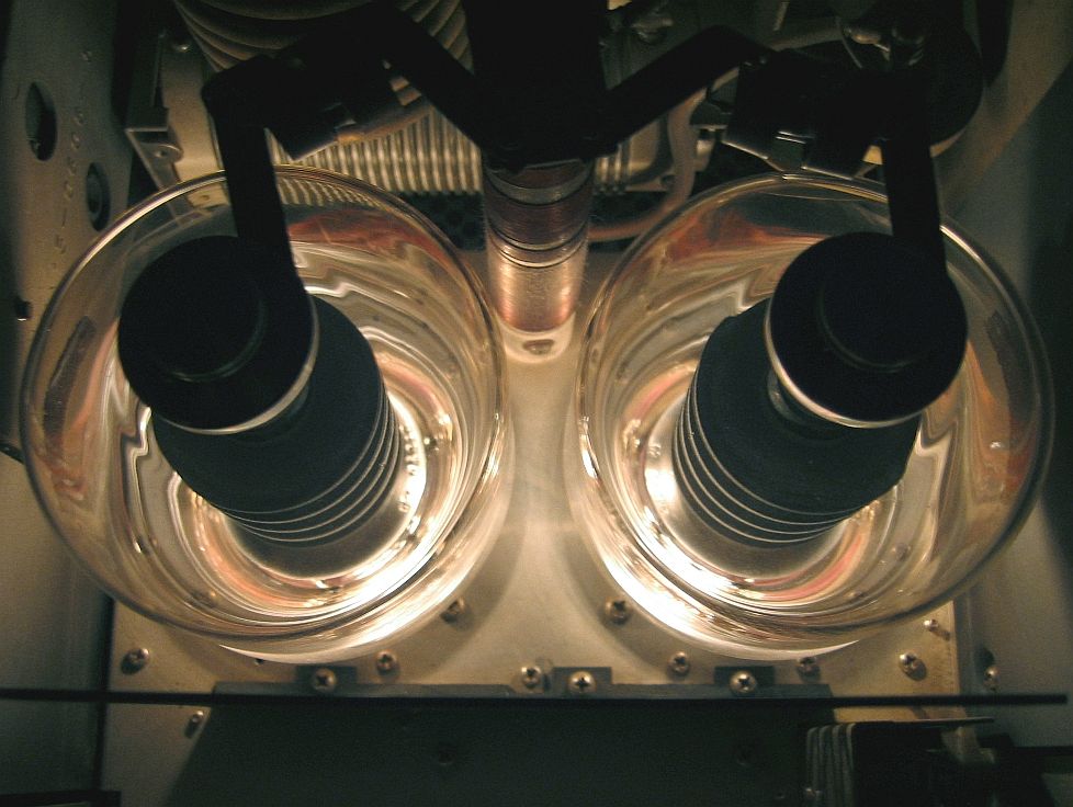
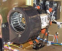
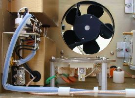
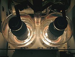
At
left, the blower near the solid state relays installed
in a QRO HF-2500DX
amplifier. At right, the small fan installed in the QRO
HF-2000 amplifier used to extract the heat
radiated by the two 3-500ZG triodes (removed from
their socket) located at the foreground. |
|
The
best blower must force air under pressure to move around corners, in
both axial and radial directions. Such an exchange is hard to get in
a cabinet containing separation plates or in which some very large
components prevent to reach the smaller but hot one located behind
them. Therefore sometimes several blowers are installed in order to
reach all corners of the amplifier, together the tube(s) section,
the RF tank and the power supply.
A
blower should be mandatory in the power supply section of the
amplifier where large components generate much heat. A smaller
blower can be installed in the RF
section to cool the heat generates in the tank. Some manufacturers
install a chimney over the tuibes which is good system, but not
mandatory from the moment when the exhaust is well separated from
the air intake area.
Like
all blowers - see blades of your computer one - they attract dust
and it should be useful to install an air filter in the air intake.
After one year you will surprise by its color.
At
last the air exhaust size and position will influence the efficiency
of the blower system. The hot air coming from inside must exit the
unit quickly and following the straightest path as possible. But
with this constraint to not blow in the direction of the user...
This means that the exhaust must be located on rear or better on top
of the cabinet, the air flowing through small openings optionaly
protected by a light grid to prevent input of particles. Avoid to
purchase an amplifier which heat is forced to flow inside, to other
components before leaving the unit, or a model which exhaust is
located in such a position (left or right seeing the amplifier in
front) that it will blow hot air on other devices located near it.
Look
and size
I
already hear some of you seeing a well designed HF amplifier saying
"Whaow, what a beautiful amp". Indeed your first feeling
seeing an amplifier will be its look, its design. Naturally
everybody is attracted by pleasant and good looking things, leaving
the "ugly" models on the side. However it should be not
the first time that this ugly model should be a great performer. So
don't trust too much in your first feeling and check well all
specifications of the amplifier of your covetousnesses. You could be
disappointed by your first feeling.
|
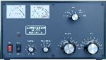
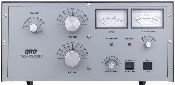
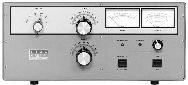
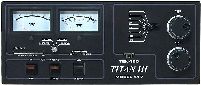
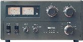
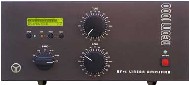
Some
well-known kW tube HF amplifiers |
|
|

|
|
|
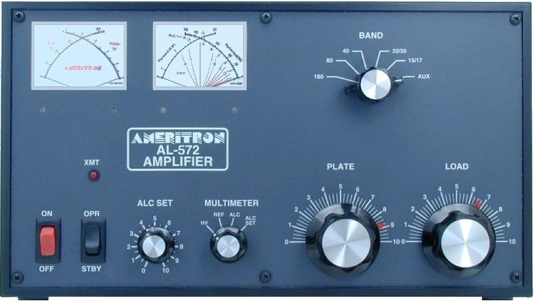
Ameritron
AL-572 |
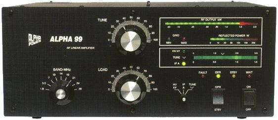
Alpha
99 |
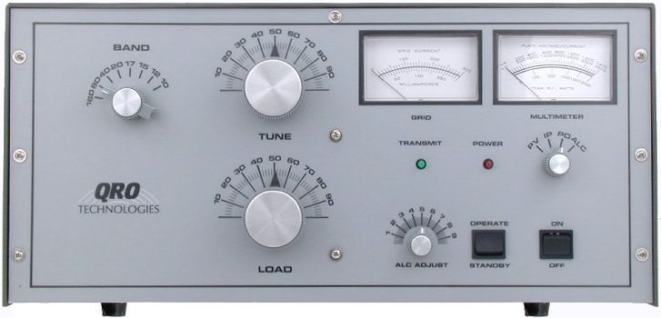
QRO
HF-2000 |
|
|
|
|
|
Commander
HF-2500 |
Ten-Tec
417 Titan III |
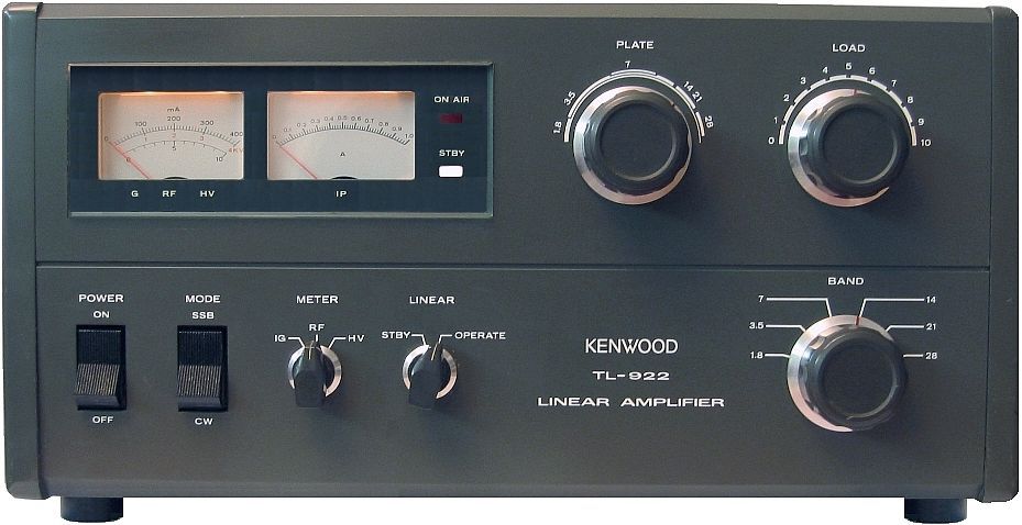
Kenwood
TL-922 |
|
|
|
|
|
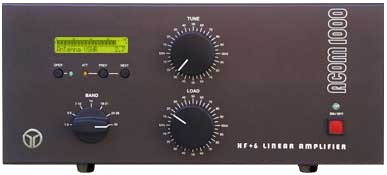
Acom
1000
|
Emtron
DX-2SP |
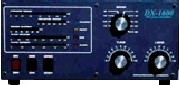
Andrews
Comm. DX-1600A
|
|
|
|

|
|
Ulvin
Tremendus II |
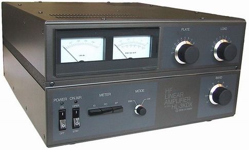
Tokyo
Hy-Power HL-3KDX |
Ranger
811H |
|
The
size of the amplifier can also be a major concern when one knows
that its mean size that can reach 45x40x25cm (18x15x10") often
smaller, plus some space left behind (30 cm or 1 ft) to dissipate
the air blown by the fan. So measure
your available place before purchasing such a gear. In addition don't forget
either that due to the large power supply a kW amplifier will be heavy with
a weight ranging from 30 to 50 kg (60-100 lbs). Placed on your desk
it can be quite bulky.
Cosmetics
size, select a model which body or front panel is hard coated of
paint, rugged, i.e. with an epoxy base or baked on thick coating.
This latter with last decades without suffering under the daylight
or after years of manipulations. If I take mine
for example, it is still like new although it was bought in the
90's. Pictures published herewith confirm its excellent state.
By
way of conclusion
I
cannot select an amplifier at your place as many parameters have
to be taken in account, the financial one being not the least. Remind
you only that a low-cost model will not last for years if you use it
regularly at high power. If it uses low quality components tell you
well that it will probably request more servicing than another model
using high quality components. A badly designed amplifier, which
blower for example doesn't extract all the heat or accumulate dust on
components, will shorten the lifespan of the unit too.
Now
if your wallet is quite slim, you can find excellent amplifiers
below $1000 and even with some luck second-hand kW models 5 to 10 years old at
$500, sold by amateurs whose regulation does no more
allow them to work with high powers. A simple
amplifier, taking advantage for decades of approved and well-known
technologies can be your companion all long your life, maybe during
much more time that the latest nec plus ultra solid-state model.
|
|
|
The
Svetlana 3-500ZG triodes standing by in the author's Kenwood
TL-922 amplifier. Clean, no dust, this rig is well
maintained and works for years at its nominal power, 80W in
and about 850W out. |
To
conclude, don't forget that a power amplifier is really a very
special gear. First, to protect your health against EMI place the
power transformer at a distance exceeding 60 cm from your body (it
is usually in most shacks). Then remember that a linear amplifier is
a dangerous peripheral, source of very high voltage. The current
required to produce ventricular fibrillation is about 80 mA and the
resistance of wet skin is about 500-1000W.
In worst case, a possibly fatal voltage could be as low as about
0.08A x 500W
= 40V DC or 32V AC (RMS). Knowing this, many domestic devices even
the ones using transistorised circuits like TV, computer or PSU,
exceed this value by a 10-factor ! Take care.
Depending how long
and at what gain you use tubes, there is some chance that they blow
up or failed for any reason, that there are manufactured in the USA
or in the eastern countries.
In input, to prevent overdrive or a failure of the ALC circuit, use
preferably the nominal power (80W PEP) instead of the maximum
(100-120W PEP) on your transceiver.
Trying
to push your amplifier to the maximum at full power input (say 120W
PEP in) is as stupid as wishing to push your car at full speed, what
has for sole consequence to shorten its livespan if not damage it !
In fact, if you experiment shut down of your amplifier after one
hour of operation, be sure that this is because you pushed it to far
during contests or working pileups at full power years long...
Unfortunately now your peripheral is worth half its price, and needs
a serious servicing to restore its normal way of functionning hours
long... at its nominal power. What you won in power will be now lost
in money !
Then it is useful to
temporary "retire" your actual tubes (say that you need
two) from the amplifier on a regular basis, say once a year if you
use it at least weekly, and exchange them for new ones. This
rotation will keep your tubes in their best condition for a long
time.
For
more Information
How
a Vacuum Tube Works, Svetlana
ND2X's
power amplifiers pages, Paul S. Goble, III
Frank's
Electron Tube Data Sheets
Richard
L. Measures, alias AG6K, articles about amplifiers
Educypedia
(RF, antennas and waves simulations)
G4FGQ
radio engineering/modelling programs
ARRL
Handbook for Radio Communications
eHam
reviews
Back
to Menu
|