|
|
|
Basics of antennas
Introduction (I) As casual listener or novice ham, the first time that you heard or read comments about antennas in publications you were probably confused with most technical terms used by amateurs. Some advanced hams think that everybody is radio engineer, they shorten some concepts and use acronyms, what does not help you in understanding the subject. Others do confuse you; they roughly read articles or ads, misunderstand some usual terms and try to translate these technical data in their language, often unappropriated for novices. To introduce you slowly in the complexity of antennas and their feeding, in the next pages we will briefly review several basic concepts : the current, the voltage, the impedance, the bandwidth, the polarization, and how the earth influences the famous radiation pattern. In other more technical articles we will discuss about antenna designs, transmission lines, SWR, radials, dB and other power units, how to assemble an antenna system, advantages and drawbacks of directional antennas, and more. Voltage and Current First of all the really basic notions... An antenna being nothing else that a powered and tuned circuit producing waves, voltage and current flow inside. So let's define these two terms in a few words. We will not enter into the electron theory although I develop this subject in depth in the French pages dealing with the quantum physics. The voltage is defined as a potential difference (pd). The electrons moving in a conductor do not move by themselves. Imagine a small pipe fill in partly with water. You can lift one end while lowering the other end. Like molecules of water moves thanks to the difference of height, electrons move from one place to another along a wire thanks to the electromotive force and the potential difference that appears in the circuit. To be clearer, say that this displacement or drift of electrons appears as soon as there is an energy level difference (or a difference of pressure when compared to water) between the two ends of the wire. Here we have to explain how flow electrons.
Electrons are charged particules( fields), and thus they are attracted by ionized atoms (atoms of copper for example with one or more free electrons). Forced into motion by the potential difference (voltage), some free electrons constituting the copper wire move from one atom to another, freeing the outer orbit of an atom to fill the hole left by another electron flying off another atom. Althoug they are hundred times smaller than atoms, counting by billions of billions, all together electrons are able to produce a current of some amplitude, all depending the voltage applied to the circuit. For your information these billions of billions of electrons in motion produce each second 1 ampere. Note that the voltage (pd) can exist without current. This potential difference is thus synonymous of voltage. It is expressed in volts (V) and in radio equipement usually in microvolts. 1 volt is defined as the pressure required to force a current of 1 ampere through a resistance of 1 ohm, hence the need to define the other units too. But all this will be much clearer of you build a small electric circuit. The current is defined as the intensity or the force of electrons flowing in a conductor, their motion being initiated by voltage. The current is thus a kinetic energy. The electrons moves always from the negative force toward the positive (although electrons move in all directions in conductors). This action takes place at speeds close to the velocity of light or almost (> 66% as fast in most conductors). In case of "chain collision" - and there are ! - we observe a shunting effect. The amount or intensity of current is expressed in amperes (A). It is defined as the number of electrons passing through a surface by unit of time. This number is the "coulomb" and measures the electrical charge. The elementary charge of a particle is e = 1.6 x 10⁻¹⁹ Coulomb. 1 ampere is thus one coulomb per second, or some 6.28 x 10¹⁸ electrons passing by.... when I told you they were billions ! Effects of current
The motion of electrons in a conductor is not without consequences. We know for example that a bulb lights and get warm, or that the needle of the compass is deflected when a powered wire passes close to it. If we invert the polarities of our circuit, we observe that the needle of our compass change of direction but that our bulb continues to light without other consequences. The current flowing in a conductor produces three main effects, two of them being polarized (their effect change according the direction of the current) : - Thermal effect, or Joule effect that heats the material exposed to current (bulb, heather, etc) - Chemical effect, the electrolyze for example where one separates oxygen and hydrogen from water. This effect is also used to charge/discharge batteries - Magnetic effect, the current creates a magnetic field. This effect is used for relays, electric motors, speakers, etc. Alternative current Direct current (DC) like the one provided by a battery is characterized by an unidirectional motion of electrons. They move continuously from one pole to another. But we know that electrons carry a negative electrical charge and produce a magnetic field as they move through space. A magnetic field is thus produced whenever an electrical charge is in motion. The strength of this field is called the magnetic moment.
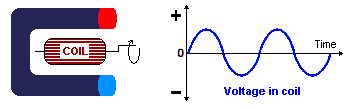
If we place a coil between the poles of a big magnet in U-shape, and connect the wires of the coil to an oscilloscop, if we turn the coil as quick as possible we observe on the display that the voltage induced in the coil is not more continuous but follows a sine curve. The rotating magnetic field has induced an electromotive force in the coil (cf. dynamo). We can thus define any alternating voltage (sine form) by the next formula : U = Um sin (ω t) where U is the voltage expressed in volt, Um the maximal voltage (peak) in volt, t the time in second, and ωt the phase angle, the coil turning of an angle α = ω t (where ω is the angular velocity expressed in radians/s, 360° = 2π rd). Impedance We all learnt in physics, when we studied the electrical fundamentals (K or L...?), that the impedance is defined as a general term that characterizes the resistance or reactance of a circuit to the flow of current. When we speak of "large power" capabilities for example of a heavy duty power supply compared to the small power provided by a AA battery cell, we mean that the first offers a "low impedance load" and the second a high impedance load, impedance meaning the opposition to the current. But to define more precisely this term "impedance" we need to introduce some more terms of electricity like resistance, reactance, capacitance, inductance, Q-factor, etc, and use some maths. As we will see all these properties are in close relation with the impedance. But don't worry, this is the only page in which I will present you so much maths and so-called "hard" concepts to understand, at least in the ham section, Hi ! It is almost mandatory to extend a few minutes on these subjects because first we will use these notions in the forthcoming chapters, but also because they come back indefinitely as soon as you speak of radio circuits. So it is better now than never.
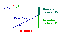
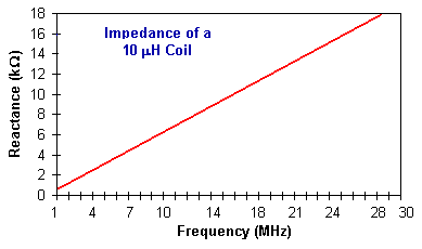
The resistance is the property of a material to resist to the flow of electrons. In is expressed in ohm (Ω). 1 ohm represents the resistance of a copper wire 0.0254 mm de diamètre (0.001"), 22.352 mm long (0.88") at 0°C (32°F). Recall that the resistance obeys to the Ohms law that defines the relationship between, voltage, current, resistance and power and that applies to DC, AC and RF. The reactance is the property of a material to resist to the flow of electrons and specially AC current or voltage in capacitors and inductors. Note that this property does not apply to direct current (DC). If we all have, at least intuitively, the feeling that selfs and condensers have an opposite action, nothing is better than a circuit and its representation in a graph like the one displayed above to well understood how this works. Taking as reference the resistance vector (red) where the phaseshift is 0, we note that the reactance is vertical, thus well shifted of 90°. The capacitive reactance is positive while the inductive reactance is negative but always 90° shifted to the resistance axis. The α angle is the phaseshift between the voltage and current. To calculate the resulting impedance Z we can use either the graphical method, measuring the length of the blue segment, or resolving the Pythagore's triangle to calculate Z. We see that the reactance can be either inductive or capacitive. What does it mean ? It refers to the opposition of inductors and capacitors to a current or voltage change. An inductive reactance appears when AC current flows through an inductance and develops a voltage that opposes a change in the initial current. This opposition is an impedance, or rather the inductive reactance XL of the circuit. It is defined as : XL = 2 π f L where f the frequency in Hertz, and L the inductance in Henry.
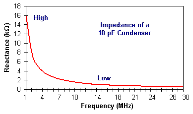
The second component of the impedance is the capacitive reactance. It appears when AC voltage flows through a capacitance and develops a current opposing a change in the initial voltage. This opposition is an impedance, or rather the capacitive reactance XC of the circuit. It is defined as : XC = 1 / (2 π f C) where f the frequency in Hertz, and C the capacitance in Farads. Note about π and complex impedance We use 2π rd (representing 360° expressed in radians) because periodic signals like AC current and voltage are easier to display in a graph showing their variations of amplitudes as a function of time along the perimeter of a circle (that spares paper, Hi !). In a resistance the current is in phase with the voltage, while its reactance is 90° out of phase with the voltage.
In the same way we use also the complex impedance because if the resistance is always greater or equal to 0, the reactive part can take any value, including negative value. As we cannot take the square root of a negative value, engineers use the imaginary numbers that allow to calculate the square root of a negative number. In rectangular coordinate form (our circle completed with 2 axis) the complex impedance is noted R ±X, j being the current (the symbol "i" being already used for the same purpose in E= RI), X the reactance and j2 = -1. Capacitance We have just seen that the electrical charge is expressed in coulomb. The component able to stock and hold the electron charge is the capacitor, aka condenser. Some are fixed others adjustable. When the current flows in a capacitor, more and more electrons enter into the component, opposing a greater electromotrice force that progressively opposes to the current flow. Soon the difference between the voltage of the power supply and the voltage on the capacitor is so reduced that practically no more current flow in the capacitor. When the capacitor voltage equals the power supply voltage no further current will flow. Of course if you apply a huge current on the capacitor feets all students know that this action ends with the explosion of the capacitor... Bang ! Very funny ! Chuut, the professor is coming back... In practice one defines a capacitance on one Farad when a capacitor is able to store one coulomb of charge at one volt input. Usually in radio circuits these components are very small and sustain much less capacitance, typically some microfarads or even some picofarads. Inductance An electrician will tell you that the inductance is the property of a circuit by which energy is stored in the form of an electromagnetic field... What does it means ? We know for one century that a conductive wire wound into a coil produces a force opposing to current flow. This counter-electromotive force displays an inductance. This force is expressed in henry (H). Like the farad usually in radio circuits we mainly encounter milli-henry (mH). Even the smallest piece of wire used in UHF has an inductance (a few milli- or micro-henry) that can be of some significance at such high frequencies. The inductance varies in proportion to the number of turns squared. Thus a coil made of two turns has an inductance value of four units, etc. The length of the coil is determined by the next formula : L = 0.394 r2 N2 / ( 9 r + 10 Lc ) where L = inductance in mH r
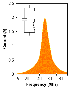
= coil radius in centimetres 0.394 is a conversion factor from inches to cm (forget it if you use inches) Q-factor We know that "Q" is present is space (the omnipotent character in "Star Trek") and in spy films (Mr."Gadget" in James Bond)... but this is also one of the most important property of both capacitors and inductors. The "Q" of capacitors is generally so high that it can be ignored, contrary to the "Q" of inductors that is of our concern. An inductor like a coil exhibits a "resistance" equivalent to an energy loss to AC or RF. The value of the reactance of an inductor (or capacitor) at the resonant frequency of a series-resonant circuit divided by the series resistance in the circuit is called the Q or quality factor of the circuit. Q determines the sharpness or selectivity of this resonant circuit according the next formula : Q = (2π f L) / R where (2π f L) is the reactance of either coils or capacitors in ohms, and R the sum of AC or RF resistance plus the DC resistance of the windings. That means that for a wire showing a DC resistance of 1 ohm, for a conductor showing an inductive reactance of 50 ohms, the Q of this coil will be 50/1 = 50. In using a lower resistance value, you will increase the Q (For example 0.5 ohm gives 50/0.5 = 100). Thus, if one keeps the DC resistant of a coil as low as possible, the larger the coil, the higher will be its Q, that represents the number of times that current circulates before is is dissipated as displayed at right. There are several other ways to increase the Q of a coil. A first way is putting a ferrite core inside the coil, but usually this system saturates in strong RF fields and is hard to design for transmission. To avoid. The second way is to reduce the bandwidth of the antenna. For example, for an antenna working on 14 MHz and showing an SWR 1.5:1, the bandwidth can be as large as 300 kHz. This Q of this antenna will be 14/.3 ~ 47. If your bandwidth is only 50 kHz, your Q becomes 14/.05 = 280 ! But conversely, that means also that an antenna system displaying a high Q shows also a high SWR, excepted in a very narrow bandwidth... Good to know ! So we have to distinct the Q of a simple coil (not loaded) from the one of an antenna system (loading coil). Take care reading advertisings... To reduce Q in an antenna system, we can either reduce lossses in improving the ground properties among other factors or add a capacitance hat above the coil. Properly designed and correctly placed, it will act like a big capacitor in lowering the resonant frequency of the antenna. But "above" does not mean to fix the cap hat directly atop of the coil as some novices and manufacturers do. Indeed, as wrote Walter Maxwell, W2DU (sk), in his articles "Another Look At Reflections" about antennas, SWR and line losses appeared in QST magazine in 1973 (Part 2, Chapter Line losses, §27) : "Models having lowest SWR are wasting power in the loading coil, because of either a low value of coil Q or excessive distributed coil capacitance, or both." In other words, placing the cap hat directly atop of the coil will increases the coil capacitance and will reduce the antenna total efficiency. In the same way, although using large coils vs small ones can increase the Q-factor on specific frequencies or on the higher frequencies, they also become very lossy at the same high frequencies. So, a compromise must be found.
The cap hat is made of an X, butterfly or a circular hat made of aluminium or copper wire in #10 or #12 gauge. Sometimes a simple "CB hat" works fine with mobile antennas as well. To find back the resonant frequency you need either to extend the antenna length or remove some of the loading coil to make the antenna more efficient. The Q will decrease with the smaller coil and your bandwidth will widen. If you have extended your antenna all the way up and can't still have the resonant with a low SWR, add a small capacitance hat some decimeters above the coil and you will be happy. Higher is Q, sharper is the resonance of the circuit. At high frequencies the resistance of a wire to AC or RF is far greater than the DC resistance. But at lower frequencies up to approximatively 1 MHz the RF travels on the outside (perimeter) of the wire instead of inside, this is the "skin effect", that decreases in the cross sectional area of the conductor and increases in the RF resistance. To reduce this effect we need to use special wiring system like the famous Litz wire to improve "Q" and get a high efficiency. The Q-factor is very important in all LC circuits like filters because their bandwidth is determined by loaded Q (loaded circuit). Take an example. If you use a typical inductor offering a Q-factor of 100, its loaded Q is about 20. The filter bandwidth is the working frequency divided by the loaded Q. At 14 MHz this is 700 kHz wide. At lower frequencies such as the 455 kHz IF it would be as narrow as 44 kHz ! Such circuits can thus be used in most IF transformers, often before crystal and ceramic filters. This concludes our definition of impedance and related terms. Resonance There is resonance when the reactance of an inductor balances the reactance of a capacitor at some given frequency, when XL = XC. When both values are of the same order of magnitude as the resistance, the current decreases quite slowly as the frequency is moved in either direction away from resonance. In series resonance the current will be maximum and will offer a minimum impedance. In parallel resonant circuits the opposite is true. Using units convenient with RF circuits, the resonance formula is : f = 106 / (2π√LC) where f is the resonance frequency in kHz, L the inductance in mH, and C the capacitance in pF. Voilà, the so-called "hard" section is over ! Your will find in the page dealing with EM radiations and RF safety some additional definitions (EM field and some units like V/m, Gauss, etc). In the next chapter we will discuss more practical matters, beginning with the bandwidth of an antenna. Next chapter
|
|||||||||||||||||||||||||||||||